57
NOTE: The two cylinder-to-crankcase nuts will be
tightened in step 9.
FI622A
C. Cylinder Head/Camshaft
D. Cylinder Head Cover/Rocker Arms
NOTE: Steps 1-4 in the preceding sub-section must
precede this procedure.
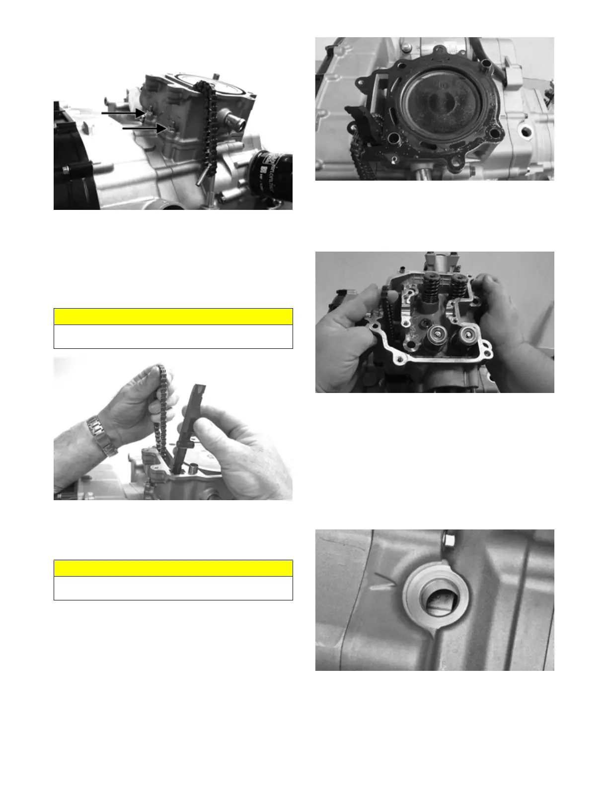
5. While keeping tension on the cam chain, place the
front cam chain guide into the cylinder.
FI621
6. Place a new gasket into position on the cylinder.
Place the alignment pins into position; then place the
head assembly into position on the cylinder making
sure the cam chain is routed through the chain cavity.
FI714
7. Install the four cylinder head cap screws with wash-
ers. Tighten only until snug. Note that the two cap
screws on the right side of the cylinder head nearest
the cam sprocket are longer than the two cap screws
on the left (spark plug) side. Tighten only until snug.
FI715
8. Install the two lower nuts securing the cylinder head
to the cylinder, one in front and one in rear.
9. In a crisscross pattern, tighten the four cylinder head
cap screws (from step 7) to 28 ft-lb (38.1 N-m).
Tighten the two lower cylinder head nuts (from step
8) to 20 ft-lb (27.2 N-m) and the cylinder-to-crank-
case nuts (from step 4) to 8 ft-lb (10.9 N-m).
10. With the timing inspection plug removed and the
cam chain held tight, rotate the crankshaft until the
piston is at top-dead-center.
FI709
11. While holding the cam chain to the front, install the
rear cam chain tensioner guide into the cylinder
head. Install the pivot cap screw and washer. Tighten
to 11 ft-lb (15 N-m).
CAUTION
Care should be taken that the bottom of the chain guide
is secured in the crankcase boss.
CAUTION
Keep tension on the cam chain to avoid damaging the
crankcase boss.