68
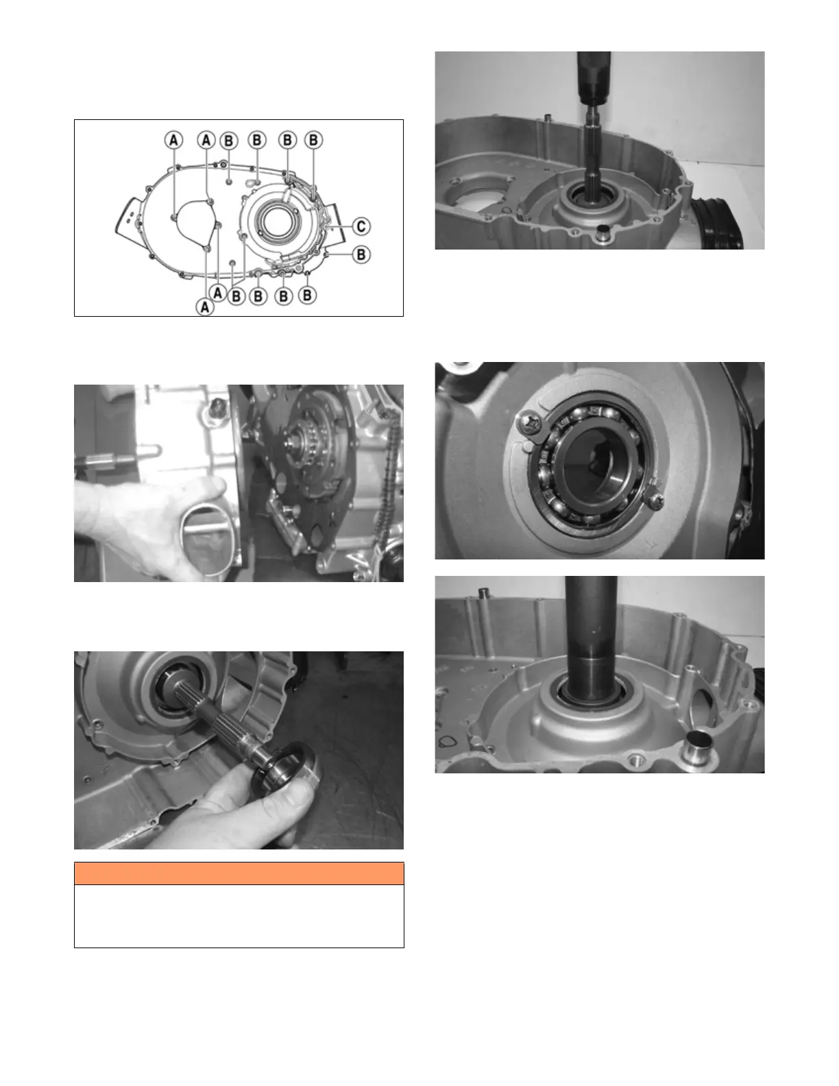
9. Remove the cap screws holding the inner clutch
cover onto the left-side crankcase half. Note the
positions of the different-length cap screws for
installing purposes.
FI726A
10. Using a rubber mallet, loosen the clutch cover; then
pull it away from the left-side crankcase half.
Account for two alignment pins and gasket.
MD1115
11. Remove the clutch housing shaft spacer and inspect
the O-ring installed inside of the spacer. Replace if
necessary.
FI732
12. Using a plastic mallet, drive the centrifugal clutch
housing out of the inner clutch cover bearing. A
press may be used to remove the centrifugal clutch
housing.
FI733
13. Remove the two Phillips head screws securing the
bearing retainers to the inner clutch cover housing.
Remove the retainers. Using an appropriately sized
bearing driver set against the inner race of the bear-
ing, press the bearing out of the clutch cover. Note
the orientation of the bearing for assembly purposes.
FI734
FI735
14. Using an appropriately sized seal driver, remove the
seal from the inner clutch cover. Note the orientation
of the seal for assembly purposes.
D. Centrifugal Clutch Assembly
E. Oil Pump Drive Gear
F. Oil Pump Driven Gear
NOTE: Steps 1-10 in the preceding sub-section must
precede this procedure.
11. Remove the one-way clutch noting the direction of
the green dot or the word OUTSIDE for installing
purposes.
! WARNING
Whenever a hydraulic press is used, a protective shield
must be in place on the press and it must be utilized to
avoid severe personal injury. Always use protective eye
wear and clothing when using a hydraulic press.