10
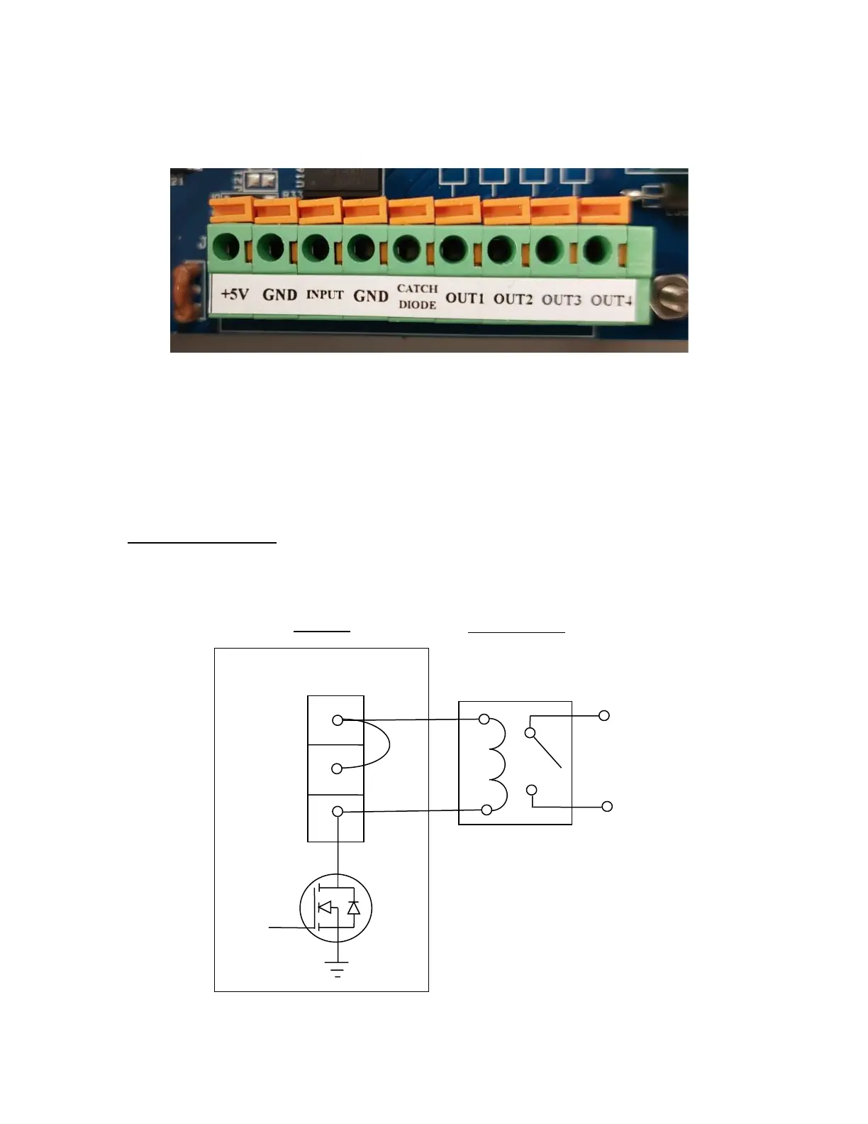
Digital I/O Connections
Connect your control cables to the Digital I/O terminal block (J4) using the diagrams below.
Digital I/O Terminal Block
The outputs (OUT1 – OUT 4) can be wired to external relays (not included) to switch inductive
loads on and off. The single remote input (INPUT) is triggered by simple contact closure.
There are two ways to drive the external relay(s):
1. Using the internal power supply from the indicator
2. Using an external power supply (not included)
Internal Power Supply
Use the +5V terminal to drive the external relay. This terminal can supply up to 500 mA of cur-
rent. The CATCHDIODE connection is not required when using solid-state relays.
 Loading...