7
INSTALLATION & OVERVIEW
Remember that the installer is ultimately responsible to assure that an installa-
tion will be and remain safe and operable under the specific conditions encoun-
tered.
The indicator must be properly configured and calibrated prior to use.
Installation of TI-1680 digital indicator
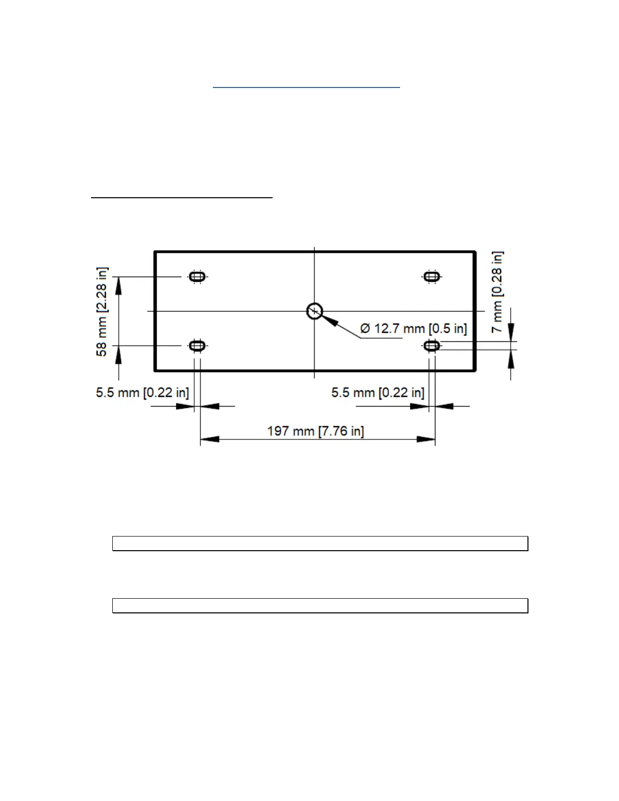
Find a suitable location for the indicator and use this handy guide to mount the included bracket
to a wall or table:
CONNECTIONS
The rear cover must be removed to make the appropriate connections to the weighing platform
and peripheral devices.
Caution! Disconnect the indicator from its power source prior to removing rear cover.
To remove the rear cover, simply remove the six (6) acorn nuts that secure it to the enclosure
and set it aside.
Caution! The rear cover contains components which are wired to the main board.
Route all cables through the PGA9 cord grips (cable entry glands). All terminal blocks are spring
loaded and are located on the main circuit board.
At each terminal, first strip away some insulation, and then push down on the orange release
tab with a small screwdriver. Insert the wire into the terminal and then allow the orange release
tab to spring back into its original position. For stranded wires, you may find that crimping on a
ferrule will improve connection integrity, as will tinning it with solder.
 Loading...