Pre-installation Testing of the MPRX
Pretest involves the following steps:
• Testing the MPRX circuit
• Connecting the antenna(s)
• Connecting the power supply
• Connecting communications
• Connecting sense input and sense output circuits
• Power and tag read capability testing prior to final installation of the MPRX
Testing the MPRX Circuit
Before installing the MPRX permanently at the site, you should test the circuit to confirm that the MPRX has
power and can read a tag that is in the tag read zone.
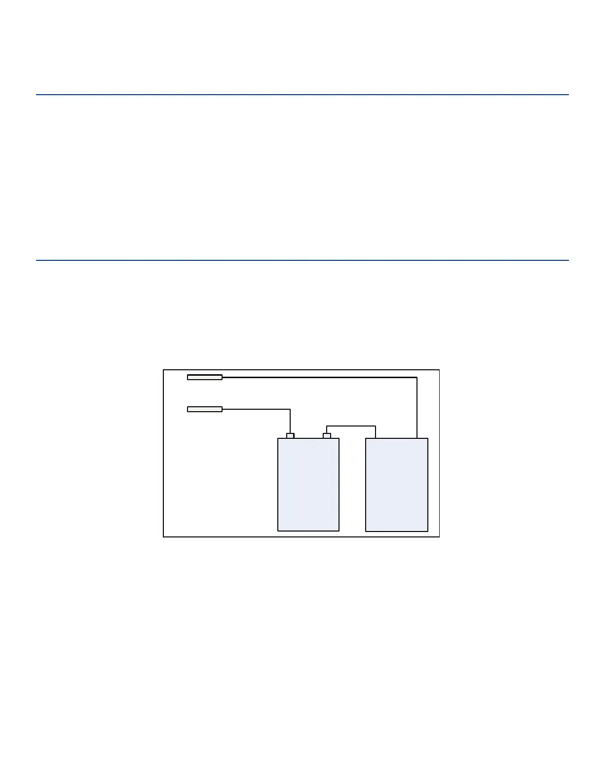
A voltage meter or audible circuit tester (buzzer) is necessary in order to test the circuit. An example test
setup diagram for onboard is shown in Figure 6. The buzzer is powered by a 9 VDC battery and is
equipped with two alligator-clip leads. When you touch the leads together, the box will produce an audible
sound.
9
VDC
Battery
6-12VDC
Buzzer
+ -
Pin 4 on
Host Connector
Pin 3 on
Host Connector
- +
Figure 6 Wiring for Audible Circuit Tester for Onboard MPRX
Chapter 2 Test Procedures
TransCore Proprietary
2–25