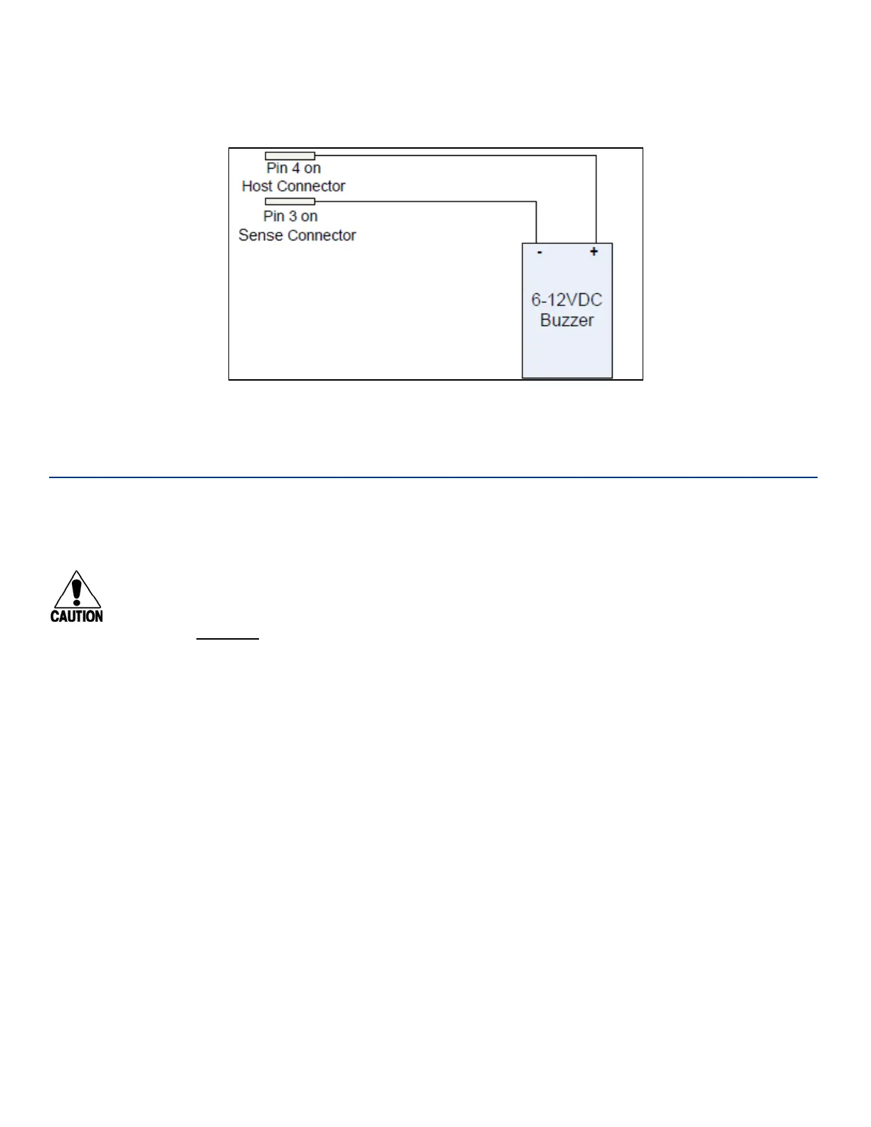
An example test setup diagram for wayside is shown in Figure 7. Voltage is present on PIN 4 so a battery
is not needed. Touching the two alligator clip leads together will produce audible sound.
Connecting the Antenna(s)
To test the MPRX, connect the antenna and power supply as described in this section.
Discharge Voltage from the Antenna
Caution
During shipping and installation, an antenna can build up a very high voltage charge. The
voltage needs to be discharged before connecting the antenna to the reader.
TransCore
strongly advises that you use adequate Earth Ground for this voltage discharge
procedure in accordance with the National Electric Code for the locale where you are installing
the MPRX.
Use these instructions to discharge high voltage from the antenna before proceeding with further
pre-installation testing of the reader.
Required Equipment
This procedure requires the following equipment.
• MPRX
• External antenna
• Grounding RF cable (long enough to reach Earth Ground source)
• N-type load (e.g., 50 Ω) or RF attenuator (e.g., 20 dB)
Figure 7 Wiring for Audible Circuit Tester for Wayside MPRX
MPRX User Guide
TransCore Proprietary
2–26