4 HD25 Hardware Interfaces
4.1.1 Mounting Provisions
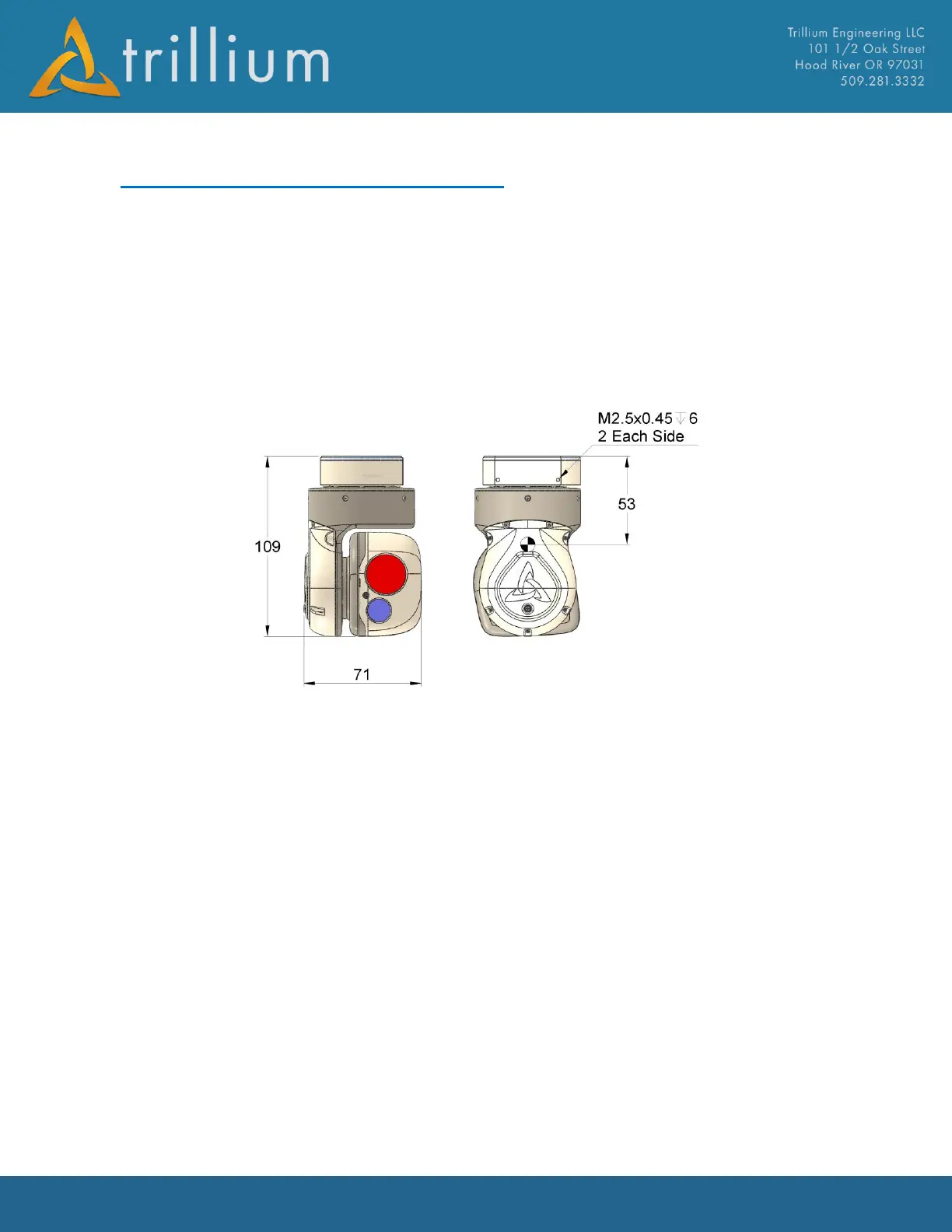
Dimensions and mounting provisions for the gimbal are shown below. Two holes tapped for
M2.5x0.45 are located on each side of the crown. All four holes should be used when interfacing to
the gimbal. When mounting the gimbal, care should be taken to ensure both the pan and tilt stages
are completely free to move; if either stage is rubbing against an interfacing part, stabilization
performance will be degraded and motors could overheat, causing permanent damage to the
gimbal. The figure also shows the approximate Cg location for the gimbal which may vary slightly
between payload configurations.
4.1.2 Interface Connectors
Both the video and GPS connectors are female MMXC receptacles; interface connectors should be
plugs with a male pin center conductor. The supported GPS antenna is an L1, 3.3V active antenna;
alternatively, GPS data can also be accepted over an Ethernet or serial interface. The GPS receiver
supports both GPS and GLONASS; for best GPS performance, an antenna that supports both
constellations should be used.
The primary interface connector on the gimbal is Ulti-mate part number CNM28L372S071S01
which conforms to MIL-DTL-32139, nano bi-lobe connectors. The recommended interface
connector is Ulti-mate NML37-2P02-30F6-18.0 S01 which has 18” long, 30 gage flying leads. Since
these connectors can have extended lead times, they are stocked and available for purchase from
Trillium, part number 50-0239. A terminated version that exposes full functionality for
development use is also available from Trillium, part number 50-2577.