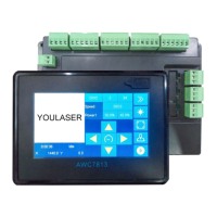
AWC7813 motion controller user manual
Continue ?"
1) When the positioning point is set too biased, the size of the graphics may
exceed the format (for the definition of the positioning point, please refer
to 3.2.7 Origin);
2) The size of the graphic itself is too large, which leads to the oversize;
3) The "relative graphic position of the laser head" (the "small blue dot" in the
display screen, see Figure4-3-1 the location of the little blue dot), If the
"small blue dot" is at the upper right of the picture, and the anchor point is
set at the far left, the file will definitely exceed the boundary;
Once the boundary is exceeded, the prompt "Beyond the border limit!
Continue?" will appear. When you click "√", the machine will continue to work
outside the format, and when you click "
", the machine will stop working.(see
Figure4-3-2 "Beyond border limit! Continue?")
Therefore, when setting the anchor point, you can combine 【X size】 with 【Y
size】 and the position of the "small blue dot" to estimate whether the graphics are
out of bounds. When the positioning key is pressed, the X and Y coordinates of the
coordinate area display the coordinates of the positioning point ( see Figure4-3-3
Graphic size and anchor point coordinates). Take the machine origin at the upper left
corner as an example. Only when the following conditions are met, can the graphics
be cut without oversize:
a) When the machine origin is at the upper left corner and the "small blue dot"
is at the upper left, X coordinate value + X size <= X axis format and Y coordinate
value + Y size <= Y axis format;
b) When the machine origin is at the upper left corner and the "small blue dot"
is at the upper right, X coordinate value-X size >=0 and Y coordinate value + Y size <=
Y axis format;
c) When the machine origin is at the upper left corner and the "small blue dot"
is at the lower left, X coordinate value + X size <= X axis format and Y coordinate

 Loading...