AWC7813 motion controller user manual
For related content, see 3.15.2 Common Parameters、3.21 Output Test。
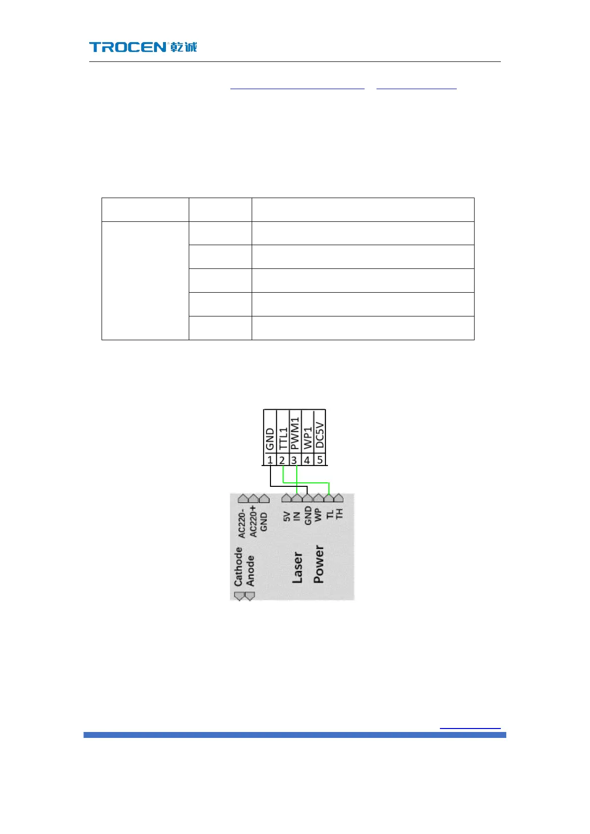
2.2.4 Laser power control port
The wiring board provides 1 laser control output.
5V power supply positive output
Water protection input signal
Power ground, output signal
The wiring diagram of the laser power control port is as follows:
Note: When the laser is a radio frequency tube, there is no need to connect to
the TTL port, just connect to the PWM port to control the laser switch and power;
when the laser is a CO2 glass tube, you need to connect the TTL and PWM ports at
the same time, which are responsible for the laser switch And power.
Please refer to the laser parameter description and settings 3.16.2 Laser
 Loading...