AWC7813 motion controller user manual
Mainly test whether all input signals are normal.
1) In Figure3-1-2 Main interface 2 interface, click 【More】→【Ins】;
2) When the peripheral is not connected normally, the input port and limit
signal port voltage is 24V, and the water protection port signal is 5V;
3) Short-circuit the corresponding input ports respectively. If the display
changes, the input ports are good. If there is no change, it may be that the
input port is broken. The specific change is from 1 to 0 or from 0 to 1;
For related wiring content, see 2.2.2 Universal input port.
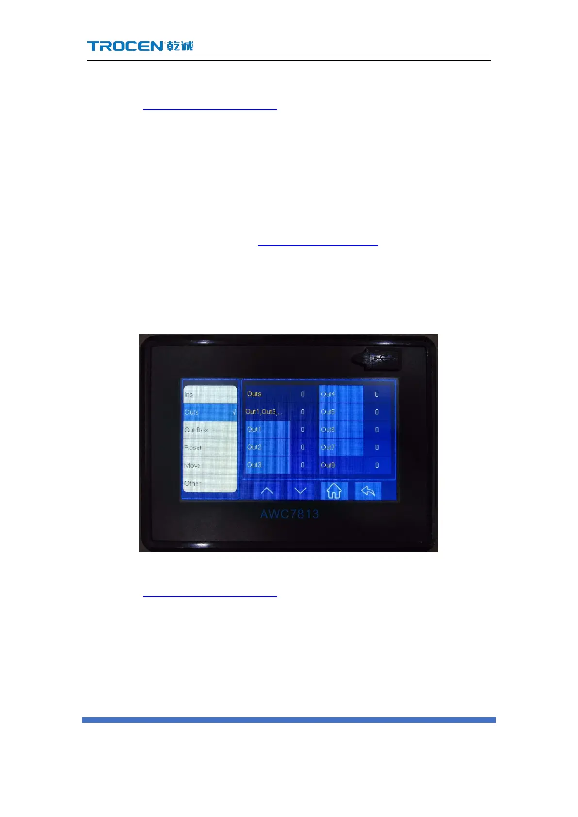
3.21 Output Test
Figure 3-21 Output test
Mainly test whether all output signals are normal。
1) In Figure3-1-2 Main interface 2 interface, click 【More】→【Outs】;
2) When the peripheral is not connected normally, the idle state of the system
is 0V, and it is 24V when working;
3) Click each individual OUT port to open or close. Click the OUT port to
display 1, output 24V; click the OUT port to display 0, output 0V. A
multimeter can be used to test whether there is 24V output. If there is no
 Loading...