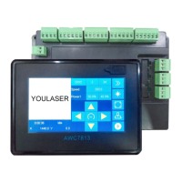
AWC7813 motion controller user manual
5. Operation process description
5.1 Machine installation and debugging process
1) Hardware installation, shaft terminal is connected to the driver, see details
2.2.5 Motor driver control port;
2) Connect the limit switch, select the appropriate limit switch, we
recommend the normally open DC24 NPN type, see 2.2.6 Limit signal input
port;
3) Install the laser power supply, if you don’t need the mainboard to control
the water protection, directly connect the laser power water protection to
the water tank or short circuit the laser power water protection, see details
2.2.4 Laser power control port;
4) Turn on the required axis power-on reset, please refer to 3.16.4 AutoReset
Settings;
5) Set 【 Limit-switch valid level 】 , 【 Limit-switch valid level 】 default is
【Low-level】, please refer to 3.16.1.5 Limit-Switch Valid Level;
6) Set 【Datum direction】, please refer to 3.16.1.3 Datum direction;
7) Set 【Key Direction】, please refer to 3.16.1.4 Key direction;
8) Debug 【 Distance per pulse 】 , please refer to 3.16.1.1 distance per
pulse(mm);
9) Set 【Range】 size, please refer to 3.16.1.6 Range(mm);
10) Set 【start Speed】, 【Max Acc】, 【Max Speed】, 【Origin Offset】, etc.
as required, please refer to 3.16.1.7 Start Speed,3.16.1.8 Max Acc,3.16.1.9
Max speed;
11) Load the file and try to cut, debug out the light, and test whether the
machine runs smoothly.
 Loading...