AWC7813 motion controller user manual
2) Z limit signal input
Power ground-output signal
Z-axis origin limit-the input signal of the
limit sensor at the minimum coordinate.
Z-axis hard limit-the input signal of the limit
sensor at the maximum coordinate.
24V power supply positive output.
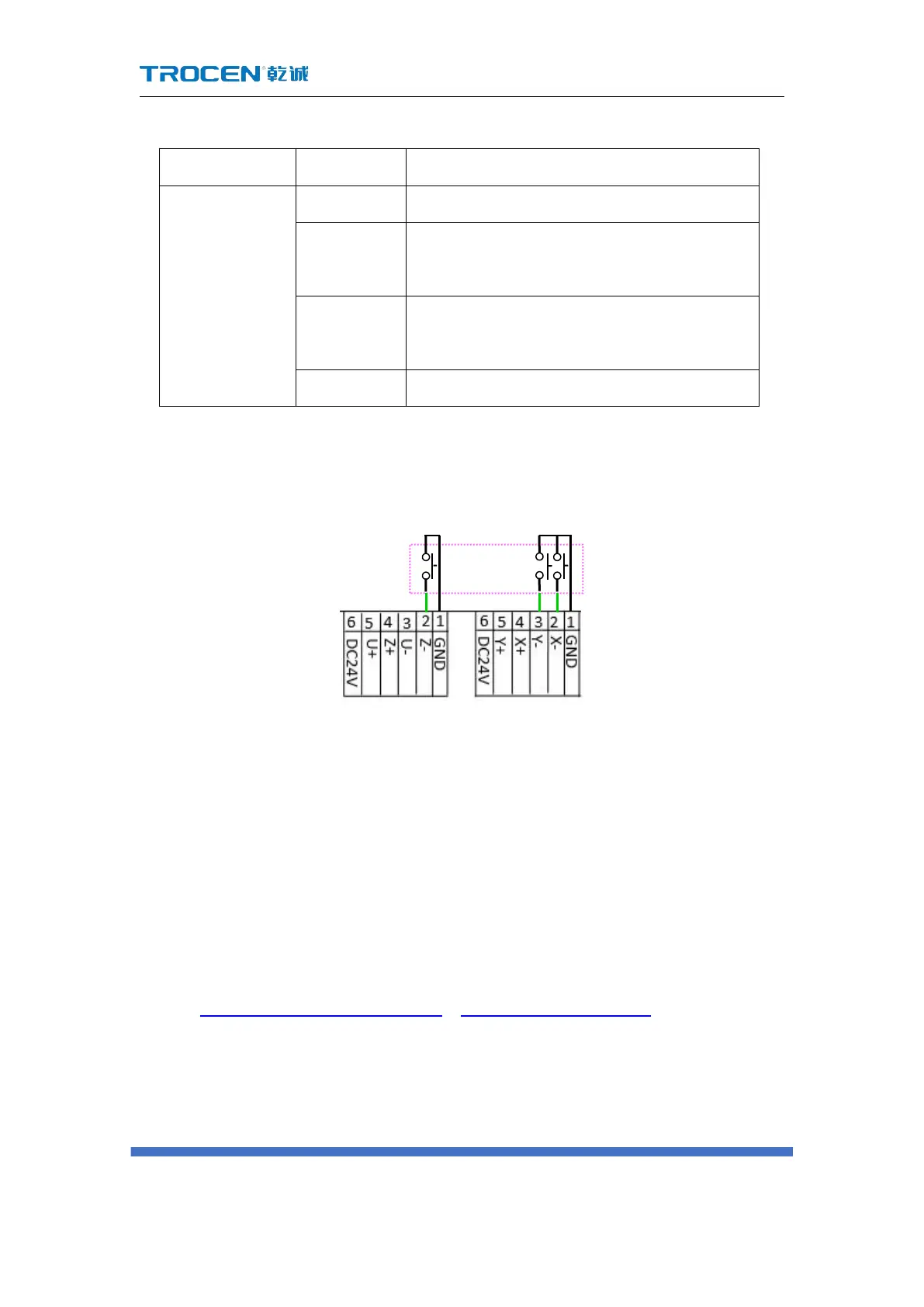
The wiring diagram is as follows:
When the selected limit switch is a normally open limit switch, the voltage of
the limit signal input port is 24V. After the limit switch is touched, the voltage of the
limit signal input port becomes 0V, and limit-switch valid level is low-level. When the
selected limit switch is a normally closed switch, the voltage of the limit signal input
port is 0V. After the limit switch is touched, the voltage of the limit signal input port
is 24V, and limit-switch valid level is high-level.
For setting the content of limit-switch valid level and hardware limit, please
refer to 3.16.1.5 Limit-Switch Valid Level、3.16.5 HardLimit Settings.
Limit switch
X+:X axis maximum
coordinate limit
X-:X axis minimum
coordinate limit
 Loading...