NORMAL.DOT Gespeichert in:G:\Support\Dokumentationen_CDs\8003Speedy\Service Manual\Servicemanual 8003.doc Gespeichert am:2003/03/10
max Version 14
Seite 39 von 87
I N D I V I D U A L M A R K I N G
fixing screws on the right and on the left side of the X-axis
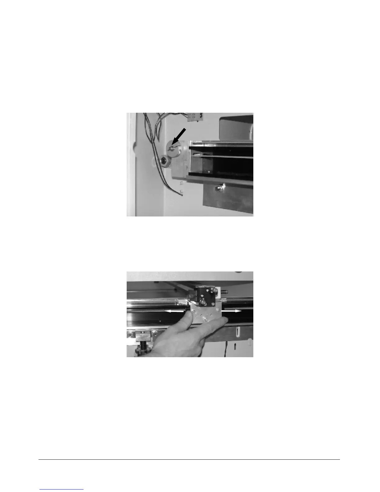
2. Open the Y axis drive shaft connector (in the maintenance compartment)
Y axis drive shaft connector
3. Perform the ruler check as mentioned above, but do not use „move laser“ to
reach 0/0, do this manually by pressing the arrow keys.
4. Turn the (right side of the) X axis if necessary, until the axis position is within
tolerance.
adjusting the angle position
5. Fix drive shaft connector and holding screws again.
Caution: When you rotate the ruler it can easily happen that the laser beam is no
longer centered at the engraving head. To make sure that this effect does not affect
the adjustment result check also the beam position at the engraving head regularely.
 Loading...