LIST OF FIGURES
Figure Title Page
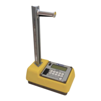
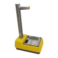
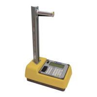
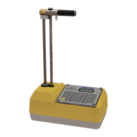
1-1 Model 3430 Gauge and Accessories .......................... 1-5
2-1
Direct Transmission Geometry .................................. 2-3
2-2
Backscatter Geometry ................................................ 2-3
2-3
Backscatter Surface Density Effects (Top Layer
Effect Curves) ............................................................ 2-4
2-4
Effect of Moisture on Depth of Measurement ............ 2-6
3-1
Model 3430 Keypad ................................................... 3-2
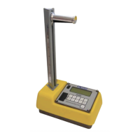
3-2
Source Rod Positions ................................................. 3-4
3-3
Standard Count Position ........................................... 3-11
3-4
Drill Rod Positioning ............................................... 3-12
3-5
Marking the Test Area.............................................. 3-13
3-6
Voids Illustration ...................................................... 3-16
A-1 Diagram of an Atom.................................................. A-2
A-2 Variation of Radioactive Emission ........................... A-4
A-3 Effect of Distance on Exposure................................. A-6
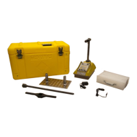
A-4 Model 3430 Gauge and Transport Case .................... A-8
C-1 Removing the Tungsten Sliding Block ................... C-13
C-2 3430 Gauge Assembly ............................................ C-17
C-3 3430 Gauge Base Mechanical Assembly ................ C-19
C-4 3430 Source Rod Handle Assembly........................ C-19
C-5 3430 Gauge Preamplifier Assembly ....................... C-21
C-6 3430 Gauge Scaler Assembly ................................. C-23