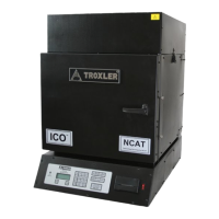
The Model 4140 Gyratory Compactor includes the electrical and
mechanical parts necessary to continuously compact hot mix
asphalt. Use Figure 1-2 to locate and identify the following parts:
1.
The power switch is located under the worktable.
2.
The control unit, located on the right side of the compactor,
contains the control electronics for the gyratory compactor. It
provides the user interface with the Model 4140 and the
interface for optional equipment.
3.
The mold, with a puck inserted, receives the asphalt for making
specimens. The molds are manufactured from hardened steel to
resist wear and pitting, while limiting weight. Sizes: 150 mm
and 100 mm.
4.
The puck inserts in the mold. The puck is also made of
hardened steel to resist wear and pitting. Sizes: 150 mm and
100 mm.
5.
The extruder removes the compacted asphalt specimen from
the mold.
6.
The dot matrix printer allows the user to print data.
7.
The parallel printer cable (not shown) connects the control
unit to the dot matrix printer.
8.
The serial cable (not shown) connects the control unit to a
serial device, like a computer.
9.
The height calibration standard (not shown), used in
conjunction with a puck, aids in calibrating the specimen height
after setting the target pressure.
10.
The Model 4140 Manual of Operation and Maintenance (not
shown) provides the operating instructions for the compactor.
11.
The specimen papers (not shown) prevent the asphalt specimen
from sticking to either the puck or the loading head. Sizes:
150 mm or 100 mm.