31
7.6 TAKING CROSS SECTION PHOTOS
After the terminal returns to its home position, open
the safety cover.
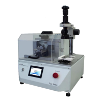
1. Take the clamp out
2. Place it on the clamp holding stand.
→ Align the clamp fitting hole with the cylindrical pin.
※Each type of clamp is designed to have 2 holes on
its body:
● Fixing hole: Used when placing the clamp on the
transfer unit.
● Fitting hole: Used when placing the clamp on the
clamp holding stand.
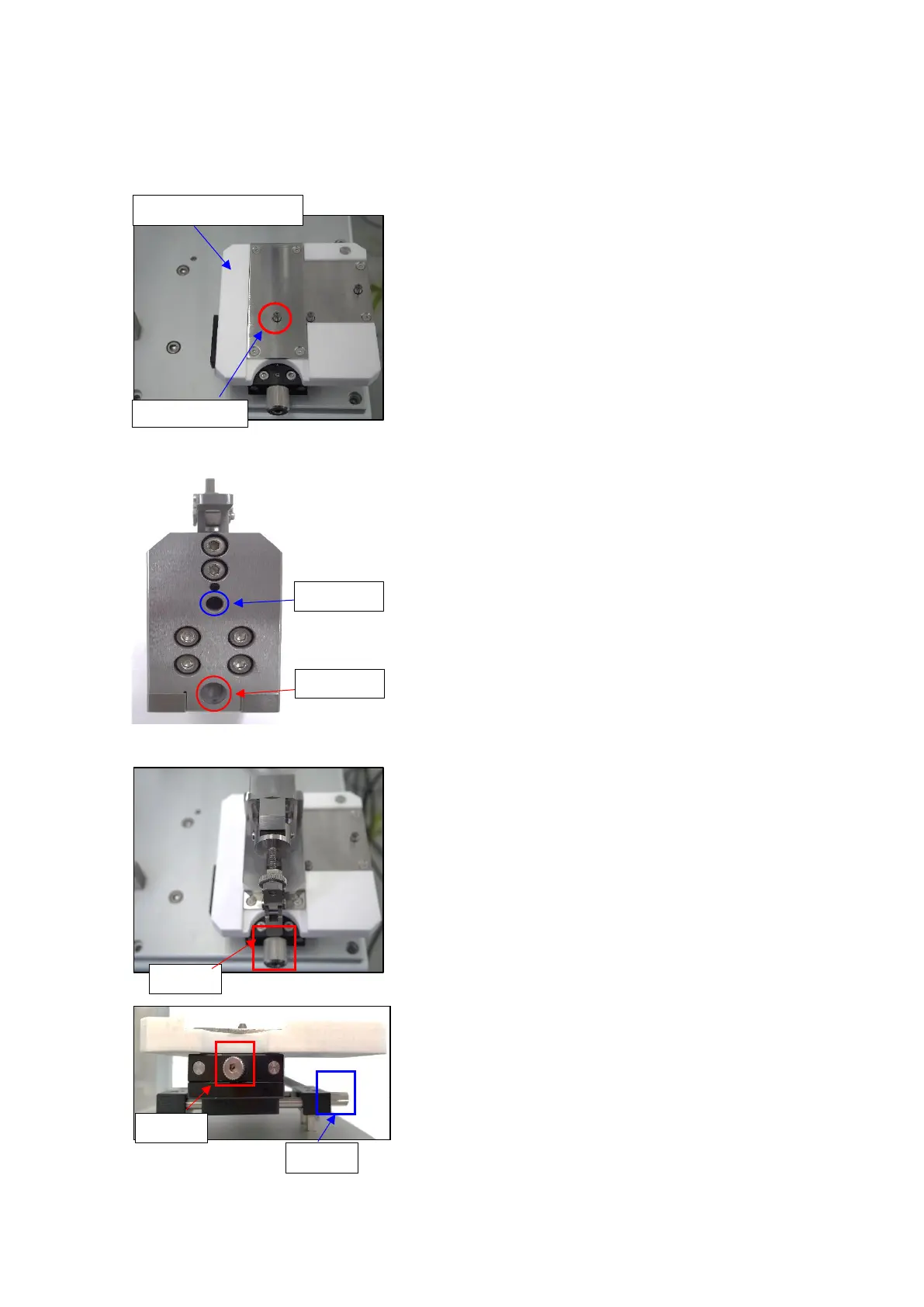
3. Adjust X and Y knobs so that the terminal cross
section is at the center of the image.
● X knob: Move left and right
● Y knob: Move up and down
Adjustment range for X and Y knobs: ±7.5mm.
4. Change the camera focus.
5. Start etching the surface
6. Take a cross section photo.