18
TTP-243 Bar Code Printer
Service Manua
l
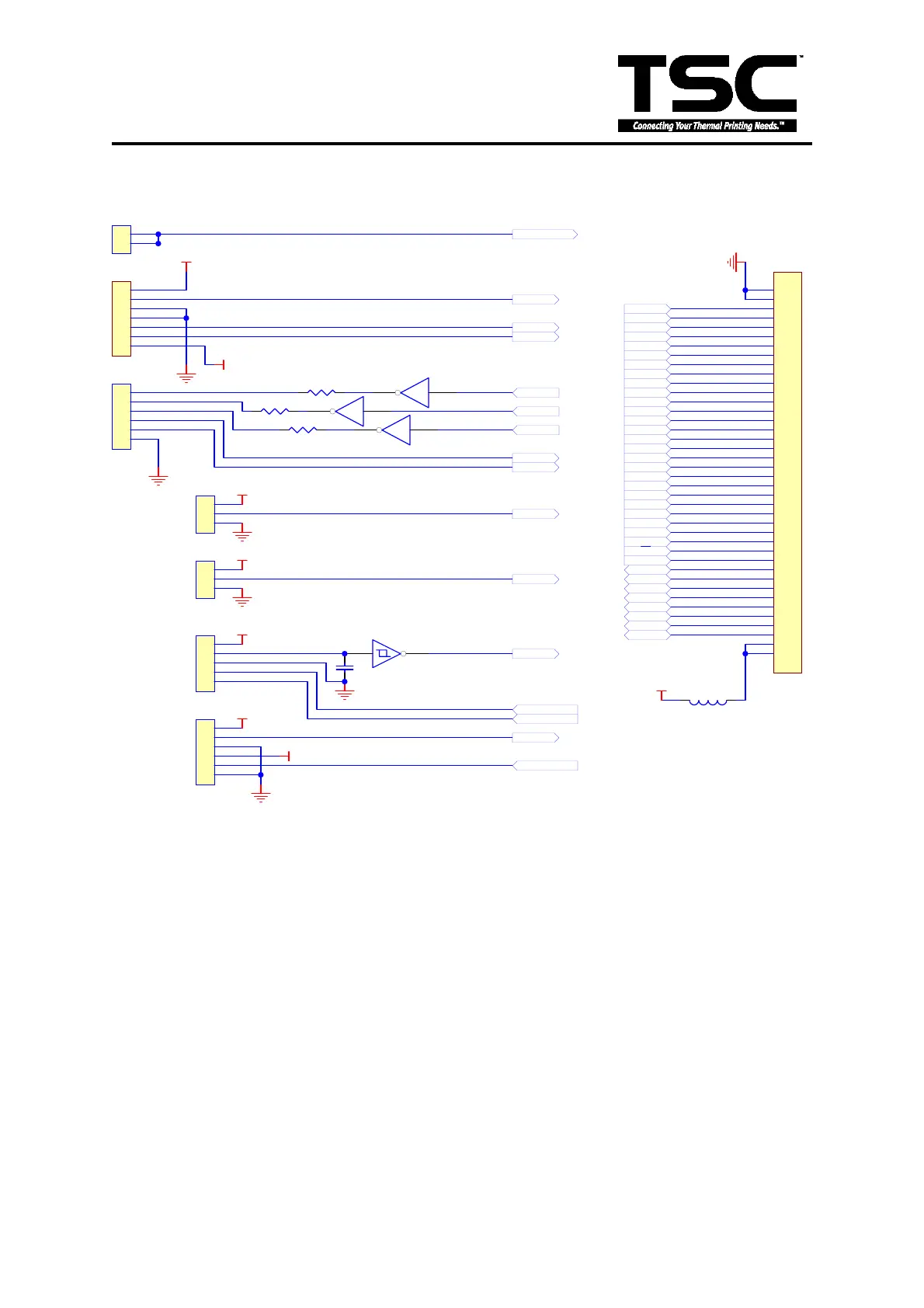
3.5 Connector Circuit Diagram
1
2
3
4
5
6
7
8
9
10
11
12
13
14
15
16
17
18
19
20
21
22
23
24
25
26
27
28
29
30
31
32
33
34
35
36
37
38
39
40
JP8
MEM.
L32
BEAD
1
2
3
4
5
6
JP1
6 PIN
12
U5A
74HC04
34
U5B
74HC04
56
U5C
74HC04
R5
100
R6
100
R7
100
1
2
3
JP2
RIBBON
1
2
3
JP4
B.L.
1
2
3
4
5
JP6
DC MOTOR
C68
0.1u
DCMB
DCMA
1 2
U11A
74LS14
1
2
3
4
5
6
JP5
6 PIN
1
2
3
4
5
6
7
JP3
ER&PEEL
1
2
PH_DERECT
1
2
JP8
PH_DERECT
MA0
MA1
MA2
MA3
MA4
MA5
MA6
MA7
A8
A9
/RESET
A10
A11
A12
A13
A14
A15
A16
A17
A18
A19
A20
A21
A22
A23
/E
R/W
OE
DO0
DO1
DO2
DO3
DO4
DO5
DO6
DO7
+5V
+24V
+5V
+5V
+5V
+5V
+5V
+5V
P65
CUTTER
P53
PH_DETECT
P45
P46
P47
P72
P60
P62
P63
P57
DC_MOTOR_A
DC_MOTOR_B
P64
GAP_EMITTER
Fig. 3.5 Connector Circuit Diagram
P45~P47 are output pins from MCU, which control the Power-on, Feed and Error LEDs
respectively. The LED lights on when the signal is “low”, goes out when the signal is
“on”.
P72: the detect pin of push button.(normally at ‘high’ level)
P60: the detect pin of feed button. (normally at ‘high’ level)
P65: the detect pin of the peel-off sensor. (normally at ‘high’ level)
P62: the detect pin of the ribbon sensor. (normally at ‘high’ level)
P63: the detect pin of the black mark sensor. (normally at ‘high’ level)
P64: the detect pin of the gap sensor and print head micro sensor. (normally at ‘high’
level)
Memory card connector
 Loading...