20
TTP-243 Bar Code Printer
Service Manua
l
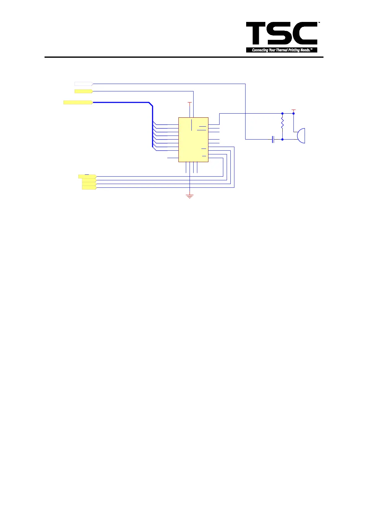
3.6 Real-Time Clock Circuit
MOT
1
NC
2
NC
3
AD0
4
AD1
5
AD2
6
AD3
7
AD4
8
AD5
9
AD6
10
AD7
11
GND
12
CS
13
AS
14
R/W
15
NC
16
DS
17
RESET
18
IRQ
19
NC
20
RCLR
21
NC
22
SQW
23
VCC
24
U14
DS12887A
DO0
DO1
DO2
DO3
DO4
DO5
DO6
DO7
DO[0..7]
DO[0..7]
+5V
DS
RTC
AS
R/W
BZ1
R50
5.6K
C66
0.1u
/RES
+5V
BUZZER
Fig. 3.6 Real-Time Clock Circuit
This is a real-time clock circuit. MCU will read the date/time and write the data when the
signal of RTC is low. AS is the address strobe signal. DS is the data strobe signal. R/W
decides whether MCU is in read mode or write mode. When R/W is at ‘HIGH’ level,
MCU reads data or time from RTC. When R/W is at ‘LOW’ level, MCU writes data to
RTC.
 Loading...