24
TTP-243 Bar Code Printer
Service Manua
l
3.9 24V/5V Converter Circuit
SW
1
SWE
2
TC
3
GND
4
Vref
5
VCC
6
Ipk
7
VDD
8
U4
34063
R11
R2 1
R3
30K
R4
10K
C5
220p
C8
10u/35V
電解電容
D1
1N5819
L2
330u
C51
470u
C11
47u/35V
L3
1u
+5V
R12
1
L23
BEAT
B1
+24V
C10
0.1u
C6
1500pF
C9
1000u/35V
SW1
SW SPDT
R56
470/2W
L14
CHOKE
D3
SR505
C82
0.01u
0.01u
L26
1
2
3
4
L4
COMM_CHOKE
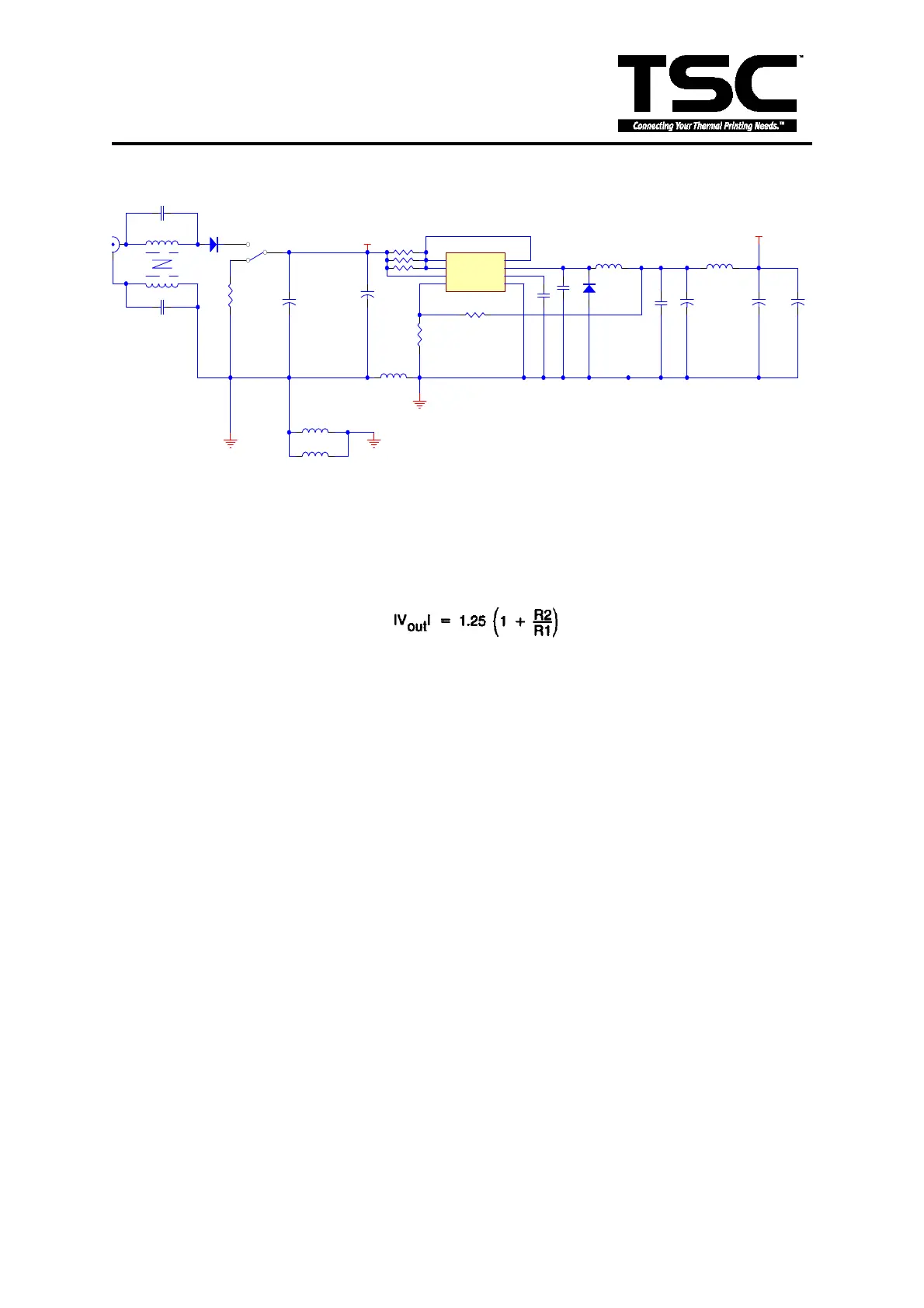
Fig. 3.10 24V/5V Converter Circuit
Figure 3.10 is the DC-TO-DC (DC24V to DC 5V) converter circuit, which is a boost
system circuit structure. U4 is the DC-TO-DC converter IC, which can convert voltage by
using PWM control mode. The output voltage is dependent on R3 and R4 and its value
is formulated as follows:
 Loading...