28
TTP-243 Bar Code Printer
Service Manua
l
3.12 Cutter Drive Circuit
Q6
TIF32C
R54
68
R55
390
+24V
D5
IN4002
CTSENS
R23
10K
+5V
A
9
B
10
CLR
11
Q
12
Q
5
Cext
6
RCext
7
U12B
74HC123
R40
150K
/RESET
+5V
1 16
9
GND
8
U20A
2003
2 15
9
GND
8
U20B
2003
3 14
9
GND
8
U20C
2003
4 13
9
GND
8
U20D
2003
C30
10u\TANT
1
2
3
4
5
6
7
JP3
CUTTER&PEEL
PEEL
+5V
D16
DSP
D17
DSP
CUTTER
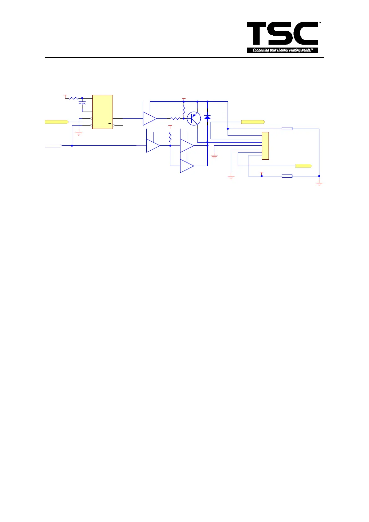
Fig. 3.13 Cutter Drive Circuit
This is the cutter drive circuit. The RESET signal is 1 when the printer is turned on.
CUTTER controls the activation of the cutter. The cutter is activated when CUTTER
signal is “low”. The sensor of cutter sends the “Hi-Lo” signal to MCU through CTSENS
pin that detects the action of cutter.
 Loading...