EasyManuals Logo

TSC TTP-244 Plus Service Manual

TSC TTP-244 Plus
40 pages
To Next Page IconTo Next Page
To Previous Page IconTo Previous Page
Page #30 background imageLoading...
Page #30 background image
27
TTP-244 Plus Bar Code
Printer Service Manual
4.7 Black Mark Sensor / Gap Sensor (Receiver) Replacement
Black mark sensor is reflection type sensor. It is connected to JP4 (3 pin connector). A
multi-meter is used to measure the signal of Pin2 to see if there is voltage variation
when black mark is detected. Before conducting the test, please issue the BLINE
command first. The printer will switch from gap sensor to black mark sensor. If there is
no voltage variation, please follow steps below to replace the black mark sensor / gap
sensor (receiver) PCB.
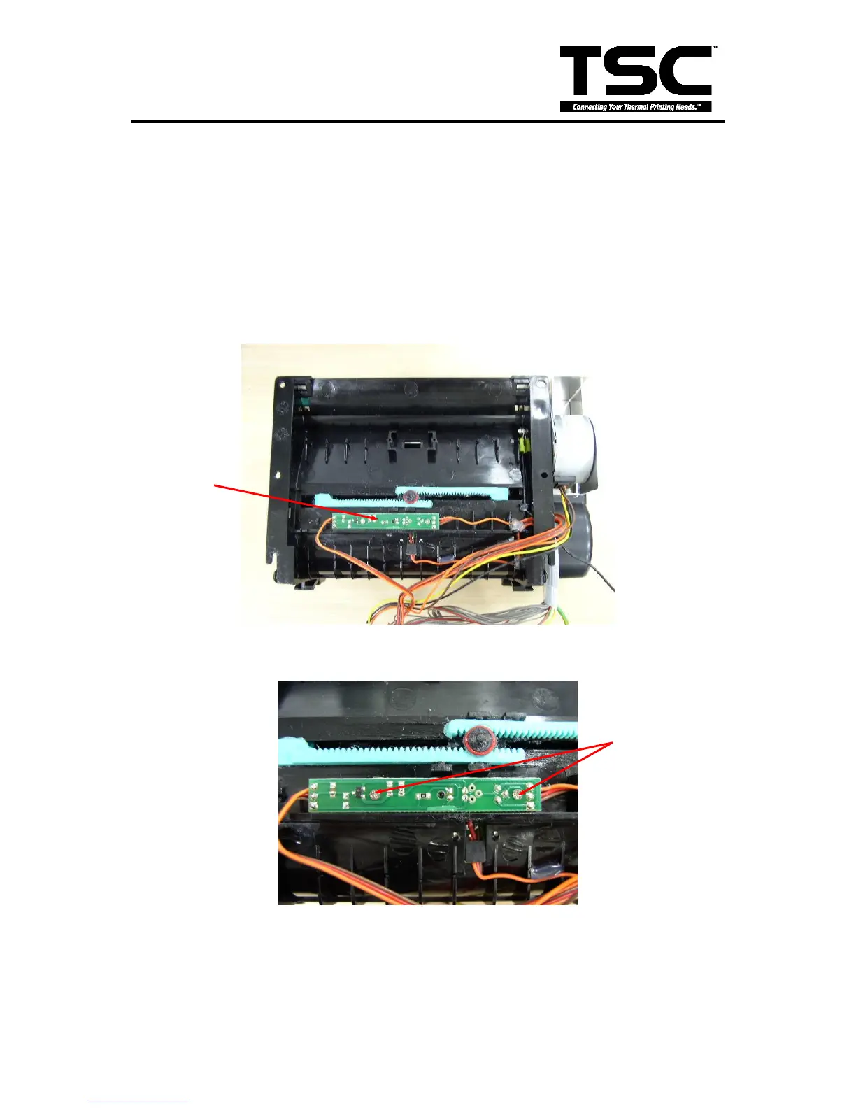
1. Follow the instructions in Section 4.2 to take out the mechanism.
2. Remove two flat tap screws and black mark sensor PCB.
3. Reassemble the removed parts in the reverse order of removal.
Screws
Black mark
sensor PCB

Other manuals for TSC TTP-244 Plus

Questions and Answers:

Question and Answer IconNeed help?

Do you have a question about the TSC TTP-244 Plus and is the answer not in the manual?

TSC TTP-244 Plus Specifications

General IconGeneral
Resolution203 dpi
Print Speed4 ips
Print MethodThermal Transfer / Direct Thermal
Weight2.5 kg
Max. Print Width4.25 inches
Max. Print Length90 inches
Processor32-bit RISC CPU
InterfaceRS-232
Label Width1 inch to 4.4 inches
Power Supply100-240V AC, 50/60Hz
Operating Temperature5°C to 40°C
Storage Temperature-40°C to 60°C
Humidity25% to 85% non-condensing
Label Thickness0.06 ~ 0.19 mm (2.36 ~ 7.48 mil)
Dimensions232 mm (W) x 156 mm (H) x 288 mm (D)

Related product manuals