38 THE CONTROL SYSTEM
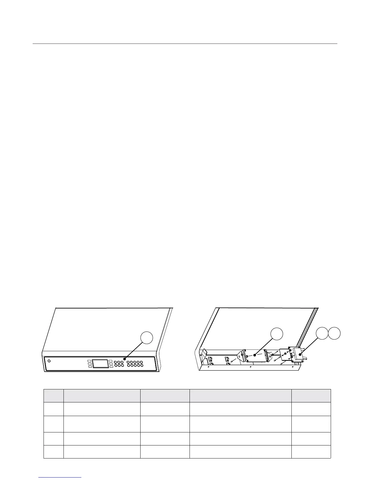
Ref # Part Description Part Number Hardware Description Hardware #
1 Cable, Smart-Card, 30 inch 100161 N/A N/A
2
Display with Ribbon Cable,
Brackets
HHB-3204
Screw, #4-40 x 1/4”, PPH, SS, Sems, Int Th
Nut, Keps Hex, #10-32, Cres, Ext Th
101520 (qty 4)
102963 (qty 2)
3 Keypad, General Market HHB-8244 N/A N/A
4 Smart Card Reader 100506 Screw, #6-32 x 1/4”, PPH, SS 101560 (qty 4)
Figure 31: Control System Components - Keypad and Display Housing
1 4
2
3
Solid State Relay (SSR)
Figure 32. The solid state relay is a 240 VAC, dual
40-amp relay. K4 (right) switches power to heater
1. K5 (left) switches power to heater 2. When the
SSR is actuated, the (-) control input will go to
0.00 VDC. When not actuated, the control input
will read -24.00 VDC.
Thermocouple – Cook Cavity
Figure 32. The cook cavity thermocouple is type K
and measures the temperature of the recirculating
impingement airflow. The thermocouple is “open”
(F7 Fault) if the display shows 999
º
F/C.
Thermocouple – Electrical Compartment (EC)
Figure 32. The electrical compartment thermocouple
is type K and measures the temperature of the elec-
trical compartment. If the temperature within the
electrical compartment is above 158
º
F (70
º
C), the
control will display an F6 Fault. It is located on the
40-pin connector.
Thermostat – Cooling Fan
Figure 32. The cooling fan thermostat actuates the
rear cooling fans when the electrical compartment
temperature reaches 120
º
F (49
º
C).
Thermostat – High-Limit
Figure 34. The high limit thermostat is a three-
pole, manual-reset thermostat with a trip point of
572
º
F (300
º
C). The thermostat interrupts power
to the main convection heater in the event of an
abnormal condition. Reset the high-limit thermo-
stat by pressing the reset button (Figure 34).
Voltage Sensor
Figure 34. For North America oven models, the
oven will detect 208 or 240 incoming voltage.
Initial voltage selection is determined before the
oven is used by the customer. However, if incom-
ing voltage for the store is different than the preset
voltage, the operator must select either 208 or 240
after pressing the On/Off key to turn on the oven.
The correct voltage will be enlarged on the screen,
identifying which option to select.
Wire Harness
The wire harness distributes power to the oven’s
electrical components. (See schematic, page 49).
 Loading...