40 THE CONTROL SYSTEM
Ref # Part Description Part Number Hardware Description Hardware #
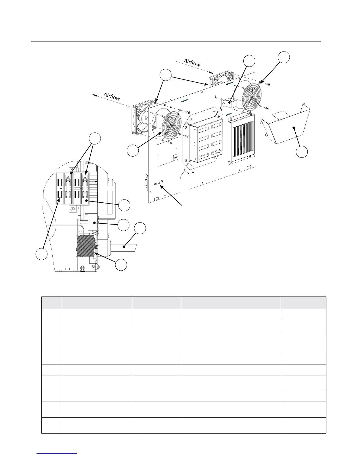
16 Baffle, Vent Tube NGC-1085 Screw, #8 x 1/2 PTRH, Type 17, Serr, 410 SS 101688
17 Cooling Fan 100516 (qty 2) Screw, 10-32 x 1/2, PPHD, Type F, SS 101694 (qty 4 per)
18 Cover, Exhaust Fan HHB-8281 N/A (attached via tabs) N/A
19 Finger Guard, Fan 100087 (qty 2) See item 13 See item 13
20 Fuse Block, 2 Pole 103548 Screw, #8 x 1/2 PTRH, Type 17, Serr, 410 SS 101688 (qty 2)
21 Fuse, 12 Amp, ATMR, Type D 100592 (qty 2) N/A N/A
22
Harness, Wiring, Jumper
(Single Phase Ovens)
HHB-8312 N/A N/A
23 Power Cord See schematic (p. 49) N/A N/A
24
Thermostat, High-Limit, EGO
300
º
C Manual Reset, 3 Pole
102075 Screw, M4 x 6, PPH SQ CO Sems, Zinc 101672 (qty 2)
25
Voltage Sense Module (60 Hz
USA Only)
100783 Screw, #8 x 1/2 PTRH, Type 17, Serr, 410 SS 101688
19
17
18
16
20
21
NOTE: Fuse configurations
vary depending on oven
model. See the schematic
(page 49) for more details.
22
23
High-limit reset button
24
25
Figure 34: Control System Components - Lower Corner of Electrical Compartment
Figure 33: Control System Components - Back Panel
16
 Loading...