14
3) FLASH memory (U17) serves as a non-volatile memory,
enabling the system to change follow-up tables during running
of program codes, and ensuring this data is not lost in case of
power failure.
— The board contains a Real Time Clock element (U12), which
serves as a clock to the system. It includes a back-up battery, which
ensures that the clock runs continuously even when the autoclave is
not powered.
— The back-up battery RAM includes a 113-byte memory component
for storing the parameters currently in use.
— The board contains a solid-state component (U18) that acts as a
system watchdog. This component detects any faulty situation
while the program code is running. It forces the micro-controller to
recheck system inputs every 1.5 seconds, this prevents the software
from becoming stuck in a program loop, that would lead to the
software crashing and a loss of control of the machine.
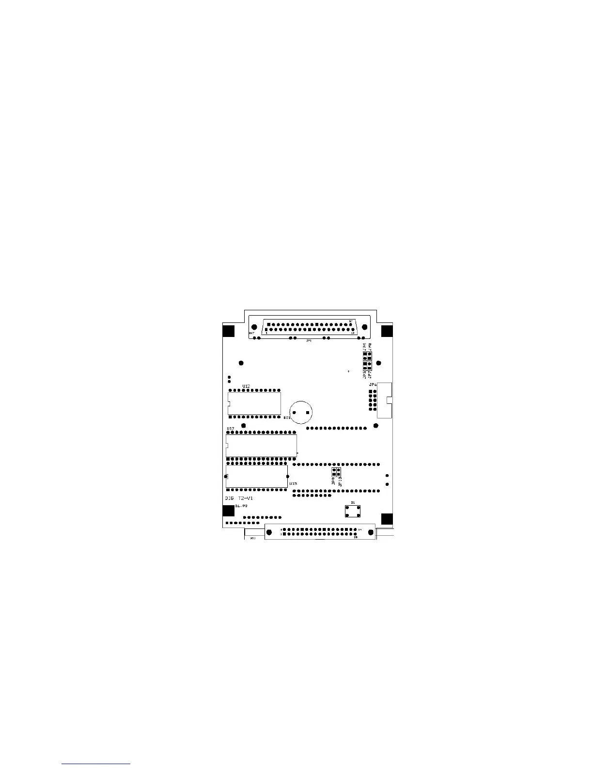
The layout of the DIG-T2 board components is provided below
DIG- T2 BOARD
— The system provides two types of communication with PC
software, RS232 and RS485. Jumpers on the DIG-T2 board need
to be set differently for each type. The default is RS232 (see also
ANL-T2 board):
1. RS232 – JP4, JP5, JP9 are closed. RS232 allows a single
communications port on the computer to communicate with a
single EHS autoclave.
2. RS485 – JP7, JP8, JP10 are closed. RS485 allows a single
communications
port, with RS485 capability, to
communicate with multiple EHS autoclaves daisy chained
together.
— The system is equipped with a hardware-reset switch (S1).