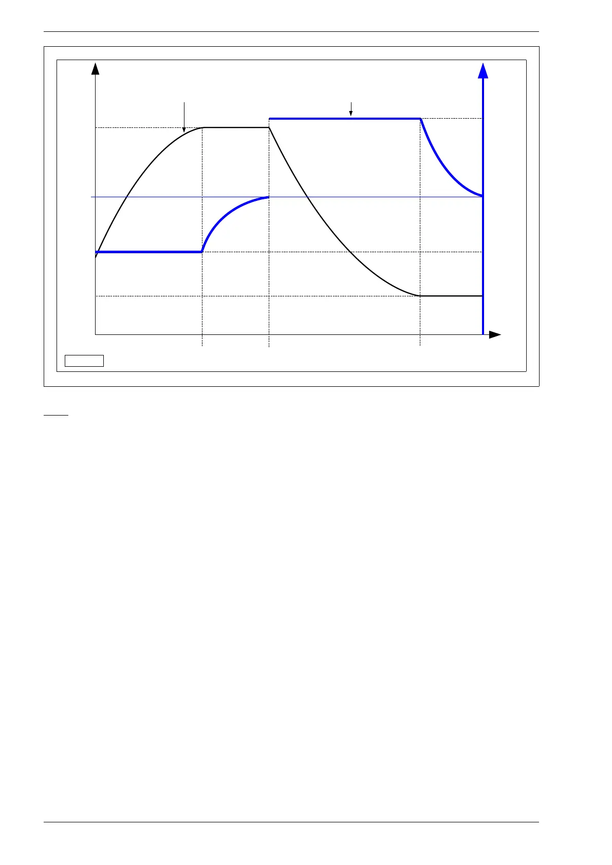
Fig. 12.1. Battery charging and discharging process
Note :
1. It was assumed that during the battery charging process the current value is negative. This is shown
in Fig. 12.1, where during the charging process the current curve is below 0A. Also on the display, in
the parameter 0.41 a negative value of the charger current means the battery charging process, and
a positive value means the discharge process.
2. The module also allows you to connect a resistor in the DC circuit as an additional electricity receiver
for the PS100-WT + BAT and PS100H + BAT systems, in which the wind energy is the source of
electricity. This resistor is activated when the batteries are fully charged in order to load the
generator and to avoid excessive speed and damage. The DC voltage level above which the resistor
will switch on is set by the parameter. 5.1.
3. The system is equipped with a hardware protection that protects connected battery banks against
deep discharge. The principle of the system consists in monitoring the voltage at the battery
terminals and turning off the charger module when the voltage drops below 39V. The power
consumption will be limited to 50A.
4. In the situation when the charger module is not operating, check the voltage at the terminals of the
connected battery. If the voltage is lower than 40V, it means that the inverter turned into mode for
battery protection against deep discharge. In this situation, disconnect the battery from the inverter
and charge it using external charger or replace it with a new one.
50 PS100 – User manual