Note:
The lock nut should be calked at a point
completely apart from the threads may damage
the threads of the bevel pinion.
10) When separating the TRB’s from the bevel
pinion,release the calking of the lock nut and
remove the bearings.
2.2 INSPECTION
1) visually check the bearing surfaces of the
bevel pinion and ring gear teeth.
Note:
The bevel pinion and the ring gear should be
replaced as a pair.
2) seriously worn or damaged parts should be
replaced.
2-3.REASSEMBLY
Reassembly the parts in reverse order of
disassembly,following these instructions.
1)Each friction surface should be coated
with grease in advance.
2)The bevel pinion and the ring gear make
a distinct pair after a mesh adjustment
performed at the factory. Consequently,
when reassembling the pair,be sure to
pair parts with a same reference number.
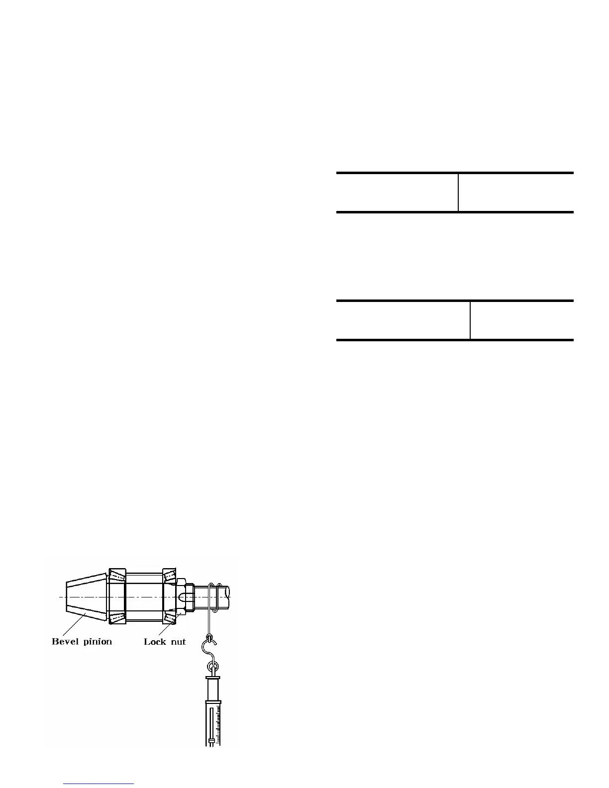
-Tighten the lock nut to the specified
starting torque of the single unit of the
bevel pinion.
Fig.6-17
Note:
As a general rule,a disassembled lock nut
should be replaced and a new one should
be installed.However,when there is no
alternative but to reuse the disassembled
lock nut assure that it can lock securely.
Note:
Measure the starting torque a manner as
shown in the figure
6 -7 Kgf-cm
(0.43-0.51 ft.lbs)
Specified starting
torque
-When any of the bevel pinion,ring
gear,TRB, collar,etc.has been replaced,
inspect the bevel pinion assembly for
thrust play in the front axle housing.
0 -0.2
(0 -0.008 in)
Specified thrust play
mm(in)
Note:
TRB and collar should be replaced as a pair.
6-8
 Loading...