4. ADJUSTMENT OF THE LINK MECHANISM.
9-8
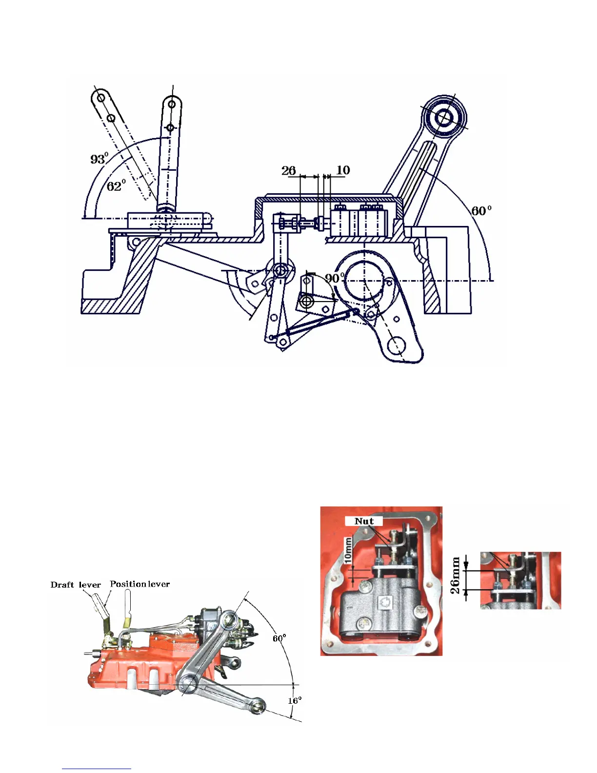
Fig.9-25
1) Adjustment of the position control link
mechanism
Place the cylinder case assembly upside so that the
lift arm can be moved freely
Point 1.Set the lift crank to the top position.Adjust
the top position installed length of the body
and plate is about 10mm or determine the
position where the angle of the lift arm
from horizontal is 60~ 61.5°.
Fig.9-26
Point 2. Fix the clearance between the body and
plate on the control valve and the casing
spool to be 10 mm,while the gap A
should be 26mm (Fig.9-27),while the
main spool is set in the neutral position.
Fig.9-27
 Loading...