9-7
Fig.9-19
3.2 REASSEMBLY STEPS.
1) Install the main control valve
2) Install the clevis comp.
3) Install the each link parts.
Fig.9-20
clevis comp
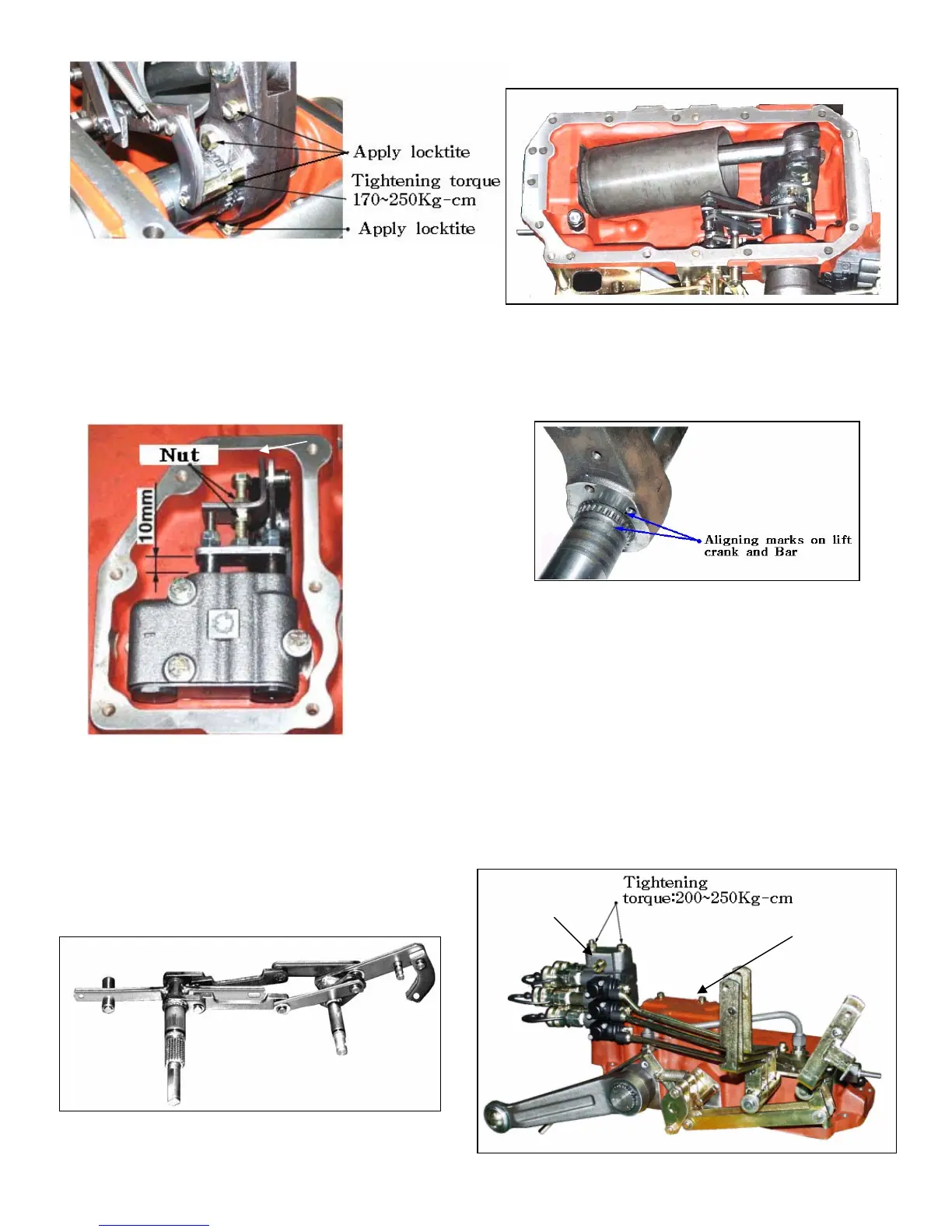
Note:
After installing the clevis to main control
valve ,make the installed length of the set the
body and plate to be 10mm(Fig.9-20)
Fig.9-21
4) Install the lift crank temporarily along with the
feed back link.Install the piston on the lift crank.
Fig.9-22
5) Install the lift shaft and lift crank together in
accordance with the aligning marks on them.
(Fig.9-23).Apply grease to the roll bush.
6) Drive the oil seal onto the lift shaft and install
the lift arm.
Note:
When installing the oil seal,take care not to allow
the oil seal lips to be damaged by the splines of
the lift shaft.
7) Install the cover main control valve and Then
install the remote control valve.
Fig.9-23
Fig.9-24
Remote control
valve
cover main
control valve
 Loading...