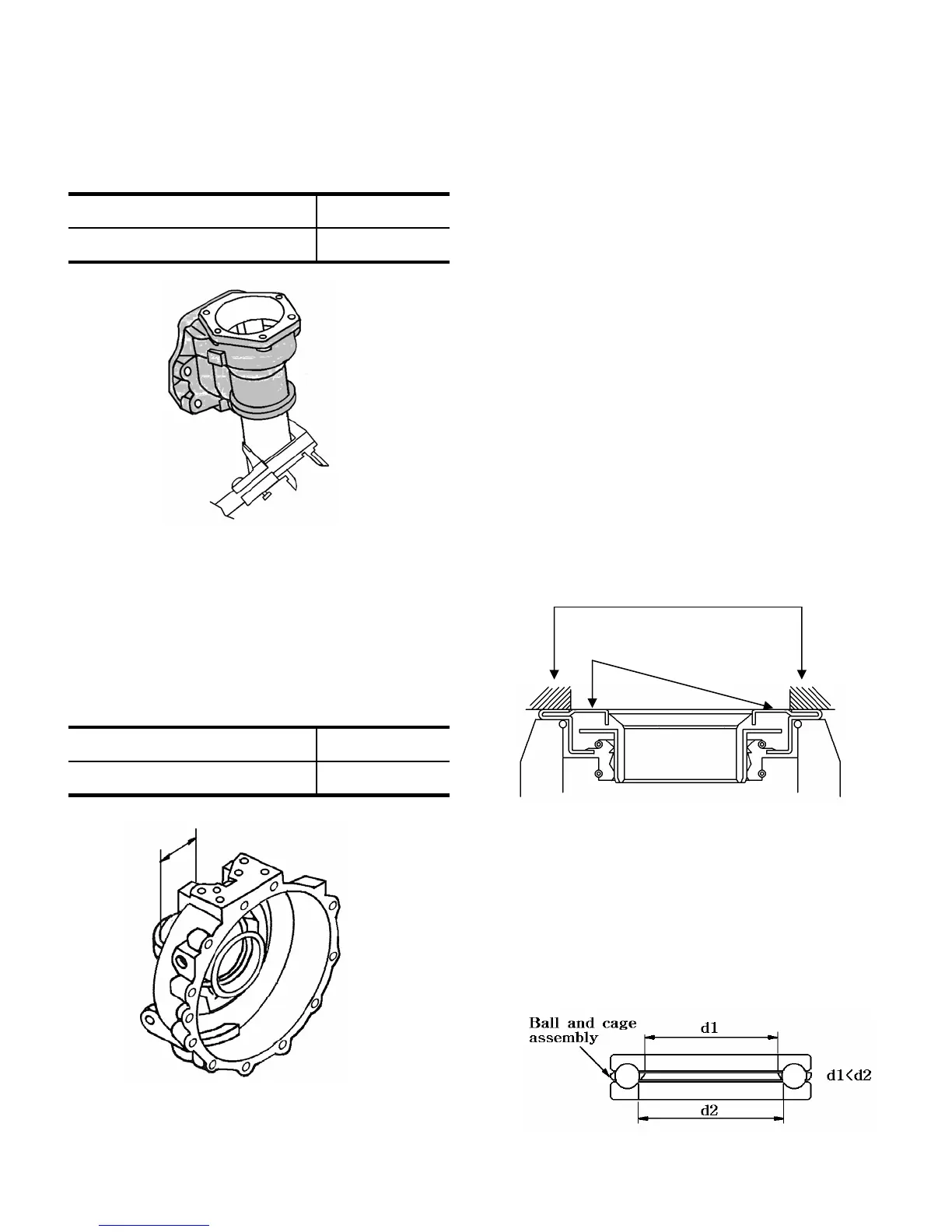
3) Final case A shaft diameter
Measure the diameter of the shaft part which
makes contact with the roll bush with a
micrometer or vernier calipers.When the
measured value is less than the usable
limit,replace the case(Fig.6-27)
Ø54.9 (2.161)Usable limit
Ø55 (2.165)Standard value as assembled
4) Final case B bush bore diameter
Measure the bore diameter of the roll bush
in the final case B with a cylinder gauge or
vernier calipers.When the measured value
exceeds the usable limit,replace the bush.
(Fig. 6-28)
Fig.6-27
Ø55.2 (2.173)Usable limit
Ø55 (2.165)Standard value as assembled
Fig.6-28
5) Inspect other bearings,oil seals,O- rings,
shafts, gears,cases,etc., and replace them
if worn or damaged
3.3 REASSEMBLY
Reassemble the parts in reverse order of
disassembly, following these instructions.
1) Apply an adhesive (THREE BOND TB1215)
to the following parts.
a.Contact surfaces between the final case B
and wheel shaft cover.
b.Contact surfaces between the final case A
and front axle.
2) When driving the seal into the bottom of the
final case A,Apply an adhesive(TB1215) to the
seal in advance.
3) When installing unitized seals on the wheel
shaft cover and the rotating part between the
final cases (A and B),apply force only to the
outer circumference of the seal as shown in
Fig.6-29 to avoid deformation.
Fig.6-29
Apply force only to the shaded parts
Take care not to deform these portions
4)The installed wheel shaft should turn smoothly.
5)The flat-seat thrust bearing,as shown in
Fig.6-30,should be installed with the larger
bore side turned downwards.Also install the
ball-cage assembly as shown in the figure .
6-12
Fig.6-30
 Loading...