9-26
5.SAFETY VALVE( Optional)
5.1 GENERAL DESCRIPTION
With the chock closed completely by turning the
adjust screw tightly clockwise,the implement
mounted on the lift is held at a specified
height.While the tractor is traveling on roads in the
condition,there is a possibility that the cylinder
pressure will rise excessively when the implement
bounces.In such a situation the cylinder pressure
can rise so high as to break the cylinder.To prevent
such an accident,the relief valve works to leak off
the fluid in the cylinder to the tank via port P and
port T to decrease the cylinder pressure
Fig.9-48
Circuit diagram
Fig.9-49
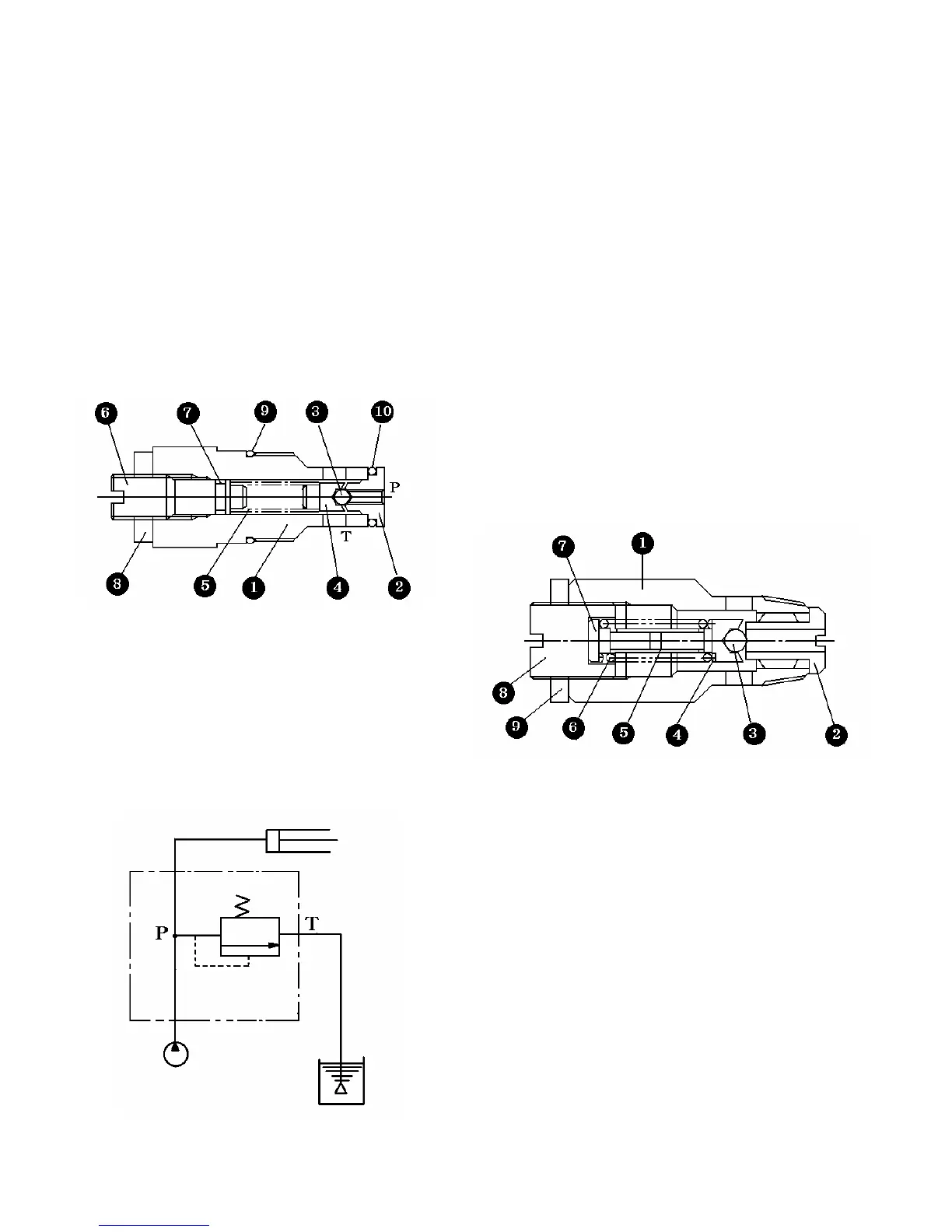
5.2 OPERATION
This valve is installed in the slow return check
valve circuit and able to be installed in the cylinder
case instead of Bolt.When the adjust screw of the
slow return check valve is closed completely,the
slow return check valve is completely closed.In this
condition,when the cylinder pressure exceeds the
regulated pressure of the relief valve: cracking
pressure,the fluid pushed up ball(3),overcoming the
force of spring(5).Then the surplus fluid is bled off
to the tank via port P and Port T.
6. RELIEF VALVE
1) GENERAL DESCRIPTION
This valve regulates the maximum pressure in
the whole hydraulic circuit.The regulated
pressure can be set with the adjust screw.
1.Body 2.seal 3.Ball 4.Spring seat
5. Spring 6.Adjust screw 7.O-ring
8.Lock nut 9.O-ring 10.O-ring
1.Body 2.seal 3.Ball 4.Spring seat
5. Sleeve 6.Spring 7.Spring stopper
8.Adjust screw 9.Lock nut
Fig.9-50
2) PRECAUTIONS FOR DISASSEMBLY
AND REASSEMBLY
(1)Tightening torque of lock nut (9)5.0∼6.0
㎏f·㎠(36.2∼43.4 ft.lbs)
(2)Install seat(2)and then tap ball(3)(5/16)
lightly so as to provide tight seating.
(3)Wrap the valve threads with sealing tape
and tighten the valve up to a specified
torque of 5-6Kgf.m(36-43 ft.lbs)
(4)Before disassembly, the current
screwing-in depth of the adjust screw
should be written down or memorized for
later reference.
 Loading...