9-4
SECTION 3. DISASSEMBLY AND ADJUSTMENT
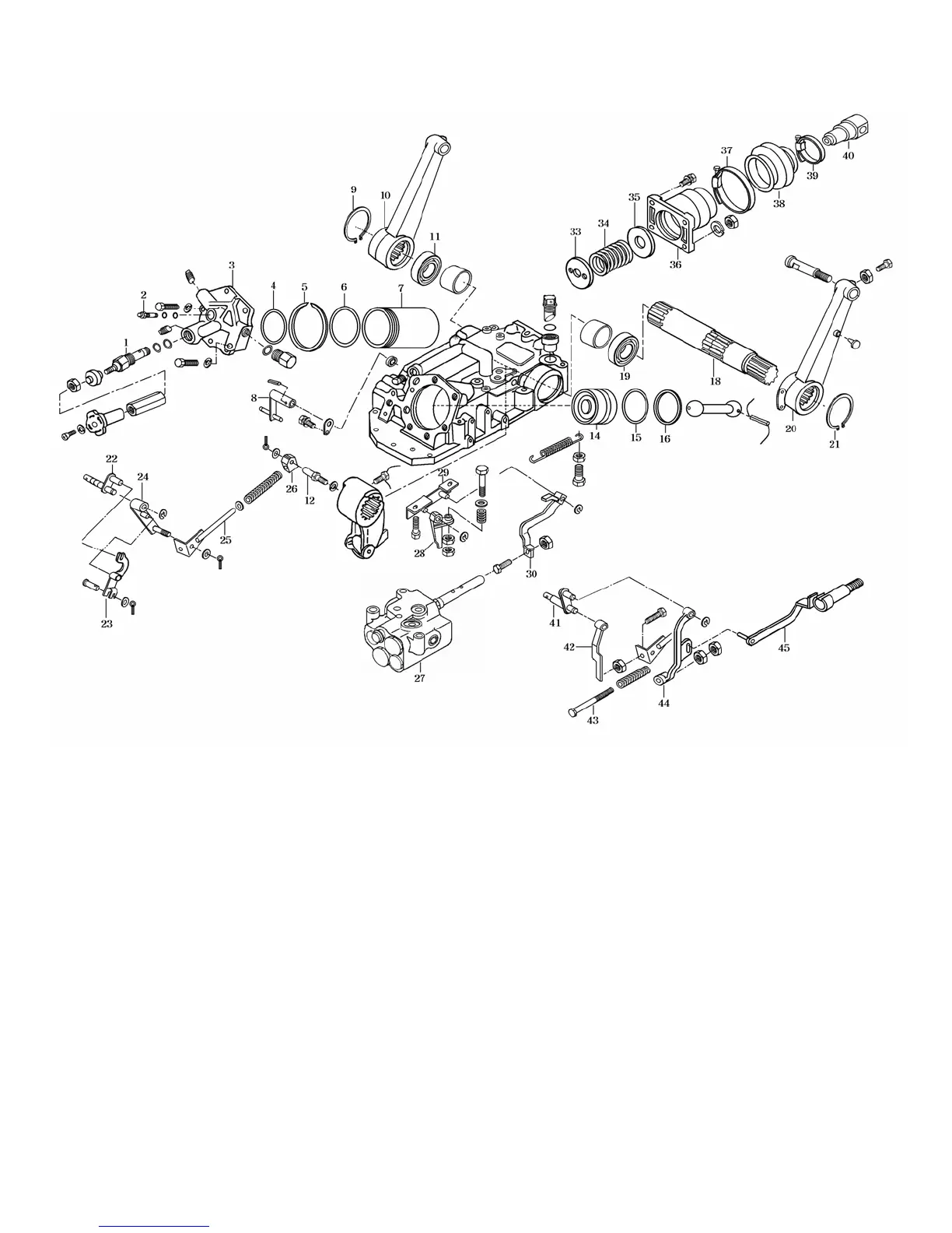
1.HYDRAULIC SYSTEM
1.Flow-control valve
(slow-return check valve)
2.Safety valve or plug
3.Cylinder valve
4.O-ring(G80)
5.Snap ring
6.O-ring(G95)
7.Cylinder
8.Position control rod
9.Snap ring
10.Lift arm(RH)
11.Oil seal
12.Pin(12X45)
13.Lift crank
14.piston
15.O-ring
16.Back up ring
17.Piston rod
18.Lift shaft
19.Oil seal
20.Lift arm
21.Snap ring
22.Position control arm
23.Arm comp
24.Feed back arm comp
25.Feed back rod comp
26.Feed back link
27.Main control valve
28.Arm
29.Holder comp
30.Pilot spool arm comp
31.Draft control arm comp
32.Stopper
33.Spring holder
34.Spring
35.Washer
36.Draft control spring case
37.Clamp
38.Boot
39.Clamp
40.Draft control boss link
41.Draft control arm comp
42.Arm
43.Pin
44.Arm
45.Draft control link comp
Fig.9-2
 Loading...