9-19
1.5. SERVICING INSTRUCTIONS.
1) Required tools
-6mm set screw wrench and torque Wrench
-19mm spanner and torque wrench
-22mm spanner and screw wrench
-conventional screw driver[3mm(0.12 in) in
blade width]
-plastic rod [Ø10mm(Ø0.394 in)]
Oil stone,cleanser,tweezers,etc.
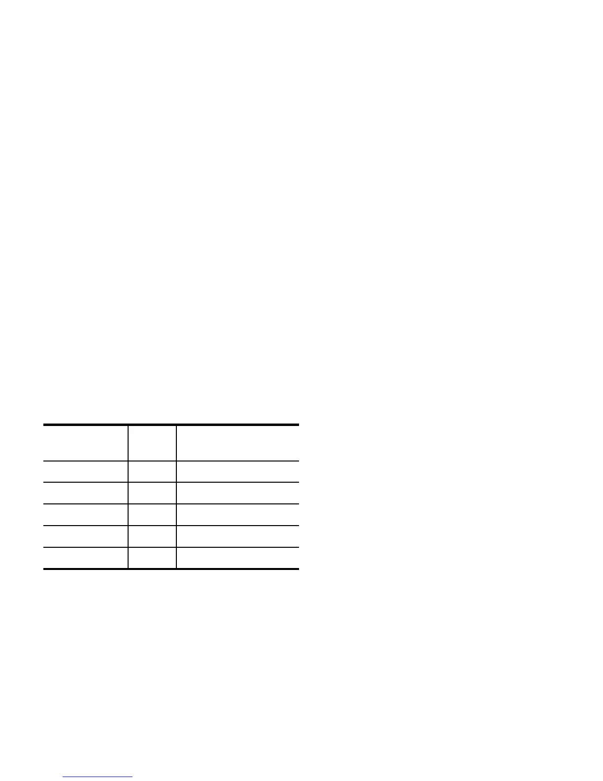
2) Tightening torque
2.5 (18.1)PT /4Sunk Plug
2.5 (18.1)M14Plug
0.8 (5.8)M6Stopper bolt
0.8 (5.8)M6Spool head
3.5 (25.3)M16Plug
Tightening torque
Kgf.m(ft.lbs)
SizeDescription
3) Disassembly
-Main spool and related parts.
Remove the snap ring E and draw out the main
spool carefully.
Note:
The main spool and spool head are screw-fitted,
so they can be separated from each other.But
they are tightened with adhesive applied,so they
should not be disassembled unless required.
-Holding check valve and related parts.
Remove the plug and take out the spring.The
poppet can come out only by slanting the casing,
and if not,remove it with pliers.
-Unloading valve(1): compensator
Remove the plugs from both sides and take out
the spring and spool.
-Unloading valve(2)
Remove the plugs from both sides and take out
the spring and spool.
Note:
The spool and stopper bolt are tightened with
each other with adhesive applied to their threads,
so they should not be separated unless required.
by removing the stopper bolt,the poppet and
spring can be taken out of the spool.
-Pilot spool and related parts.
Remove the plugs from both sides and take out
the spring and push rod.
The pilot spool set can be pushed out from the
push rod side with a Ø10 mm(Ø0.394 in) rod.
When pushing,put the rod on the sleeve,not the
spool.
Note:
The spool and sleeve cannot be separated from
each other.
4) Lifting to neutral shifting(unloading process)
While the piston is rising,the configuration of the control valve is the same as in the lifting position.
But when the piston stops rising at a required position,spool(A) returns to neutral position. In this
state,orifice(7) is closed and orifice (6) is opened,so the pressure in chamber(13) becomes lower than
that in chamber(15) and spool (B) (unloading valve 1) is shifted leftwards a little to let pump delivery
fluid flow out through orifice(35).As pump delivery pressure becomes lower than cylinder holding
pressure,passage(27) becomes higher than that in chamber(18).Consequently spool (H) (unloading
valve 2) is shifted rightwards and chamber(22) is connected to port T4,Chamber (13) is also connected to
port T4 through passage(16),chamber(19),orifice(20),chamber (21),and chamber(22),so the surplus
pressure in chamber(130 is released.In short when the control valve is shifted from the lifting position to
the neutral position,The pressure in chamber(13) on the right-hand side of spool(B) is forced to release to
port T4 and thus unloading operation is performed positively.
 Loading...