Operating Manual for UTD2000/3000
(Note: Input signal still shall be connected to
channel circuit under such mode althoug
waveform is not
Figure 2 3 Synchronous obstruction of DC and
C components of signal
㧙
18
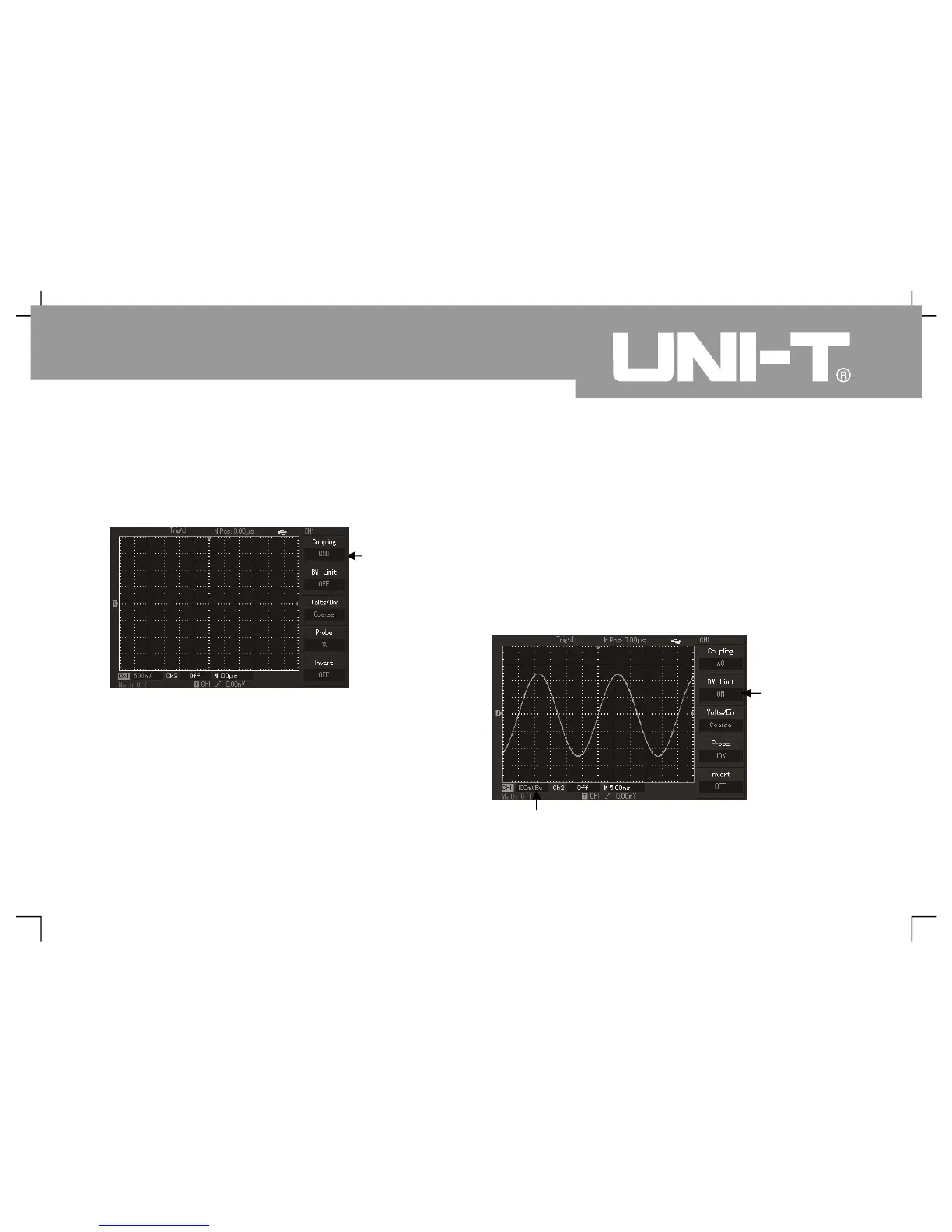
Ground couplin
Setup of cha nnel bandwidth l imit㧦
Input one sine signal of about 40MHz for CH1 as an
example. It has to press [CH1] to open CH1 channel
then pr ess [F2] to set bandwidth limit to OFF
Channel band width is full band width to pass
through high-frequency components contained by
measured signal. Waveform display is also s hown
Figure 2 Waveform display when closin
bandwidth limi t
㧙4
Bandwidt
Bandwidth suppression icon