12.INSTALLATION
108
12. INSTALLATION
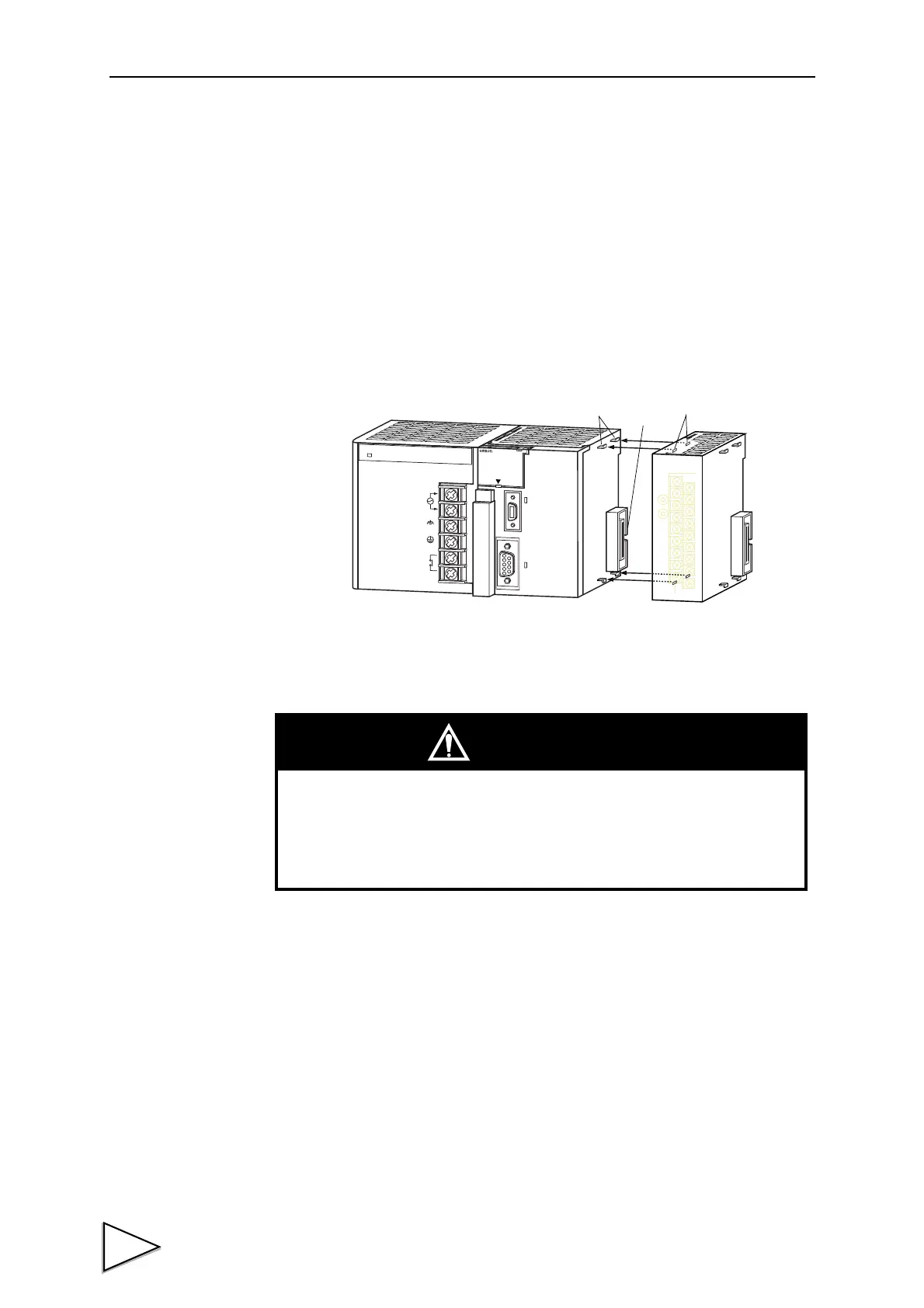
12-1. Connection with CJ1 Unit
Multiple of CJ1 units can be connected by simply engaging connectors and
locking the slider. Add an end cover to the unit installed to the right most unit.
1 Engage the connector properly to connect units.
CJ series do not require base unit. Each unit can be connected to each other using
the integrated side-mount connector.
P
A
205R
P
O
W
E
R
INPUT
A
C1
0
0-
24
0V
L2/N
L1
DC24
V
A
C24
0V
OUTP
U
T
RUN
P
E
R
IP
H
E
R
A
L
ERR/
ALM
RUN
I
NH
COM
M
PRPHL
C
ON
T
R
OLL
E
R
C
J1G-C
P
U
4
4
S
Y
S
MA
C
P
R
O
G
R
A
M
MA
B
LE
PORT
O
P
E
N
B
U
S
Y
M
C
P
W
R
Connector
Fooking hole
Fook
CAUTION
・Never fail to turn off the system before starting system assembly.
・When replacing a unit, remove the assembled unit as a
whole before replacing one of them.