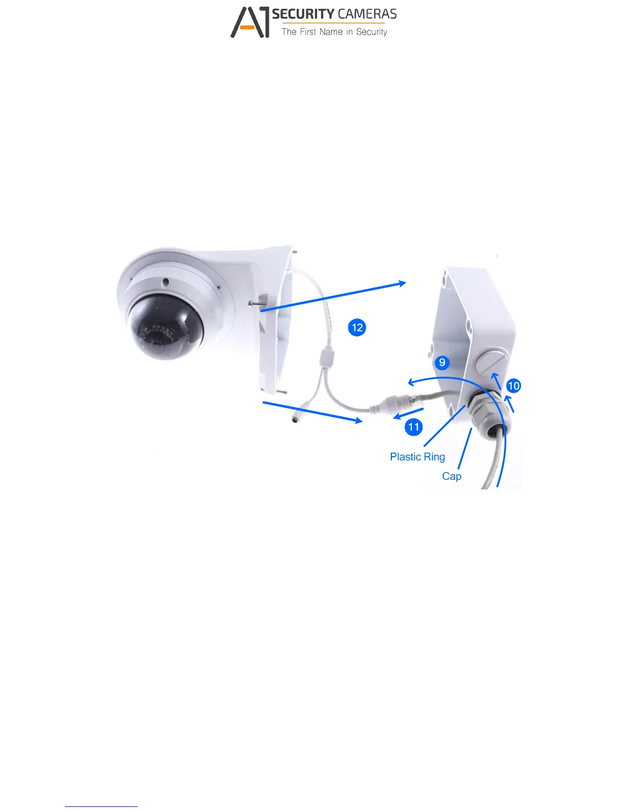
11. Thread the Ethernet cable through the PG21 conduit connector and the power box as
shown in No. 9, Figure C-9.
12. Rotate the plastic ring to secure the conduit connector to the power box. Screw in the cap
as shown in No. 10, Figure C-9.
13. Plug the Ethernet cable to the RJ-45 connector of the camera as shown in No. 11, Figure
C-9.
14. Screw the wall mount bracket to the power box as shown in No. 12, Figure C-9.
Figure C-9