Appendix
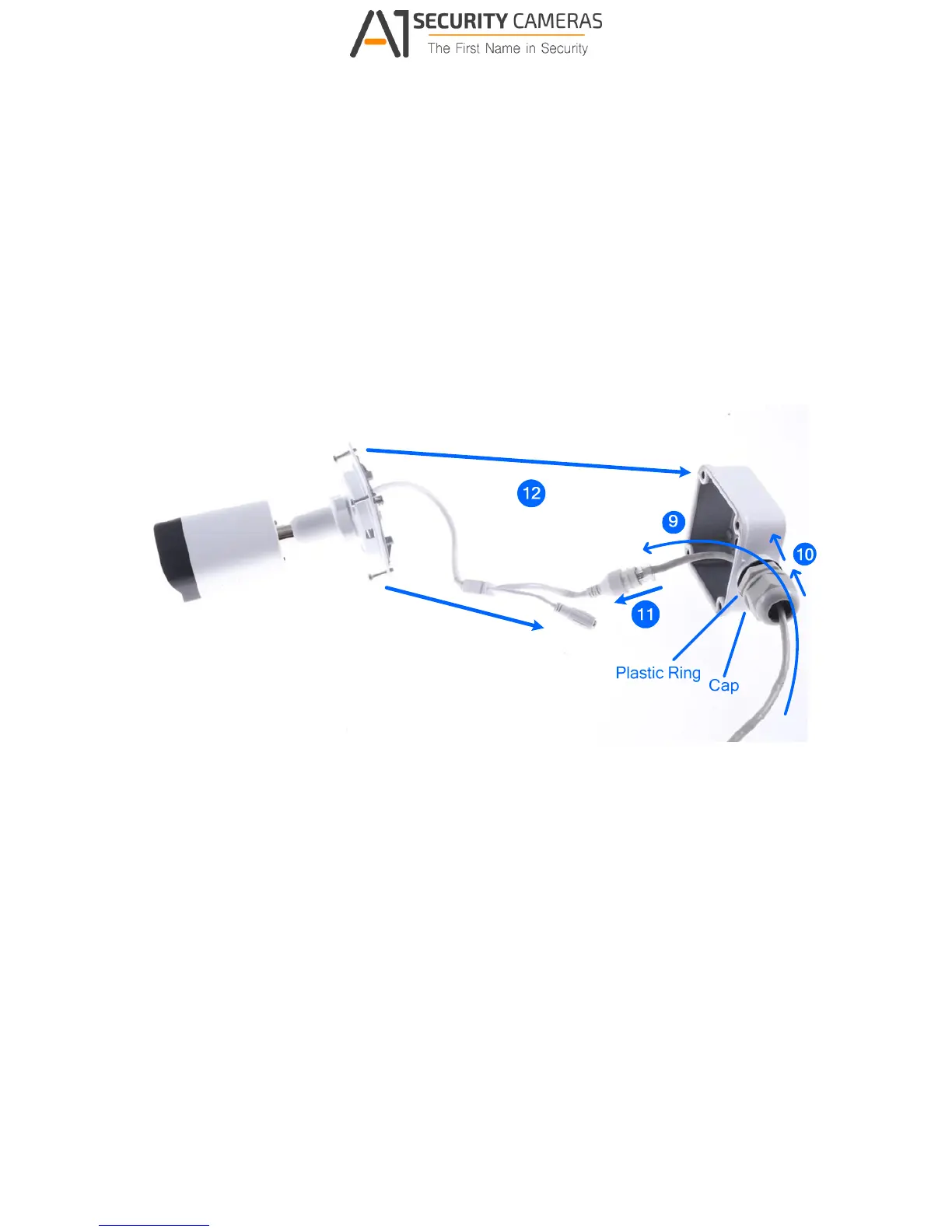
8. Thread the Ethernet cable through the PG21 conduit connector and the wall mount box
as shown in No. 9, Figure D-7.
9. Rotate the plastic ring to secure the conduit connector to the wall mount box. Screw in
the cap as shown in No. 10, Figure D-7.
10. Plug the Ethernet cable to the RJ-45 connector of the camera as shown in No. 11, Figure
D-7. To waterproof the Ethernet cable, see F.Waterproofing the Cable.
11. Arrange the cables.
12. Screw the wall mount box cover to the wall mount box as shown in No. 12, Figure D-7.
Figure D-7