ENGLISH
- 17 -
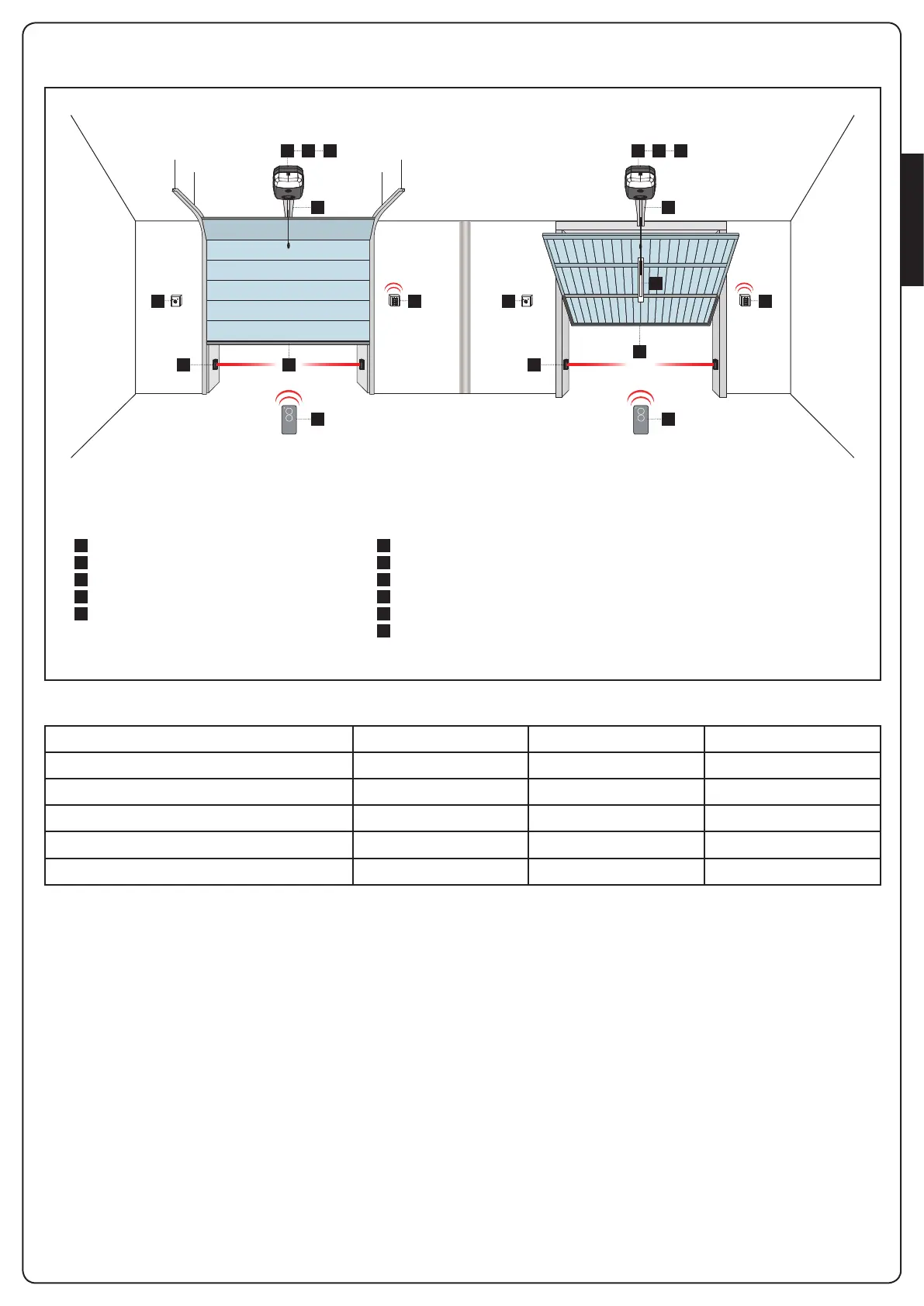
3 - INSTALLATION LAYOUT
1 4 5
2
3
A D
C E
1 4 5
2
3
A D
F
B
E
A
B
C
D
E
F
1
2
3
4
5
Key switch
Internal photocell
External photocell
Digital radio switch
Safety edges
Adaptor bracket for counterweight balanced doors
Motor
Transmitter
Guide chain / belt
Control unit
Receiving module
COMPONENTS ADDITIONAL ACCESSORIES
LENGTH OF THE CABLE < 10 metres from 10 to 20 metres from 20 to 30 metres
Power supply 230V 2 x 1,5 mm
2
2 x 1,5 mm
2
2 x 2,5 mm
2
Photocells (TX) 2 x 0,5 mm
2
2 x 0,5 mm
2
2 x 0,5 mm
2
Photocells (RX) 4 x 0,5 mm
2
4 x 0,5 mm
2
4 x 0,5 mm
2
Key switch 2 x 0,5 mm
2
2 x 0,5 mm
2
2 x 0,5 mm
2
Safety edges 2 x 0,5 mm
2
2 x 0,5 mm
2
2 x 0,5 mm
2