ENGLISH
- 19 -
6 - INSTALLATION
1. Disassemble the door’s locking system.
2. Measure the door, and at exactly half its height mark the
reference points on the upper crossbeam and on the ceiling to
facilitate positioning of the guide section bar.
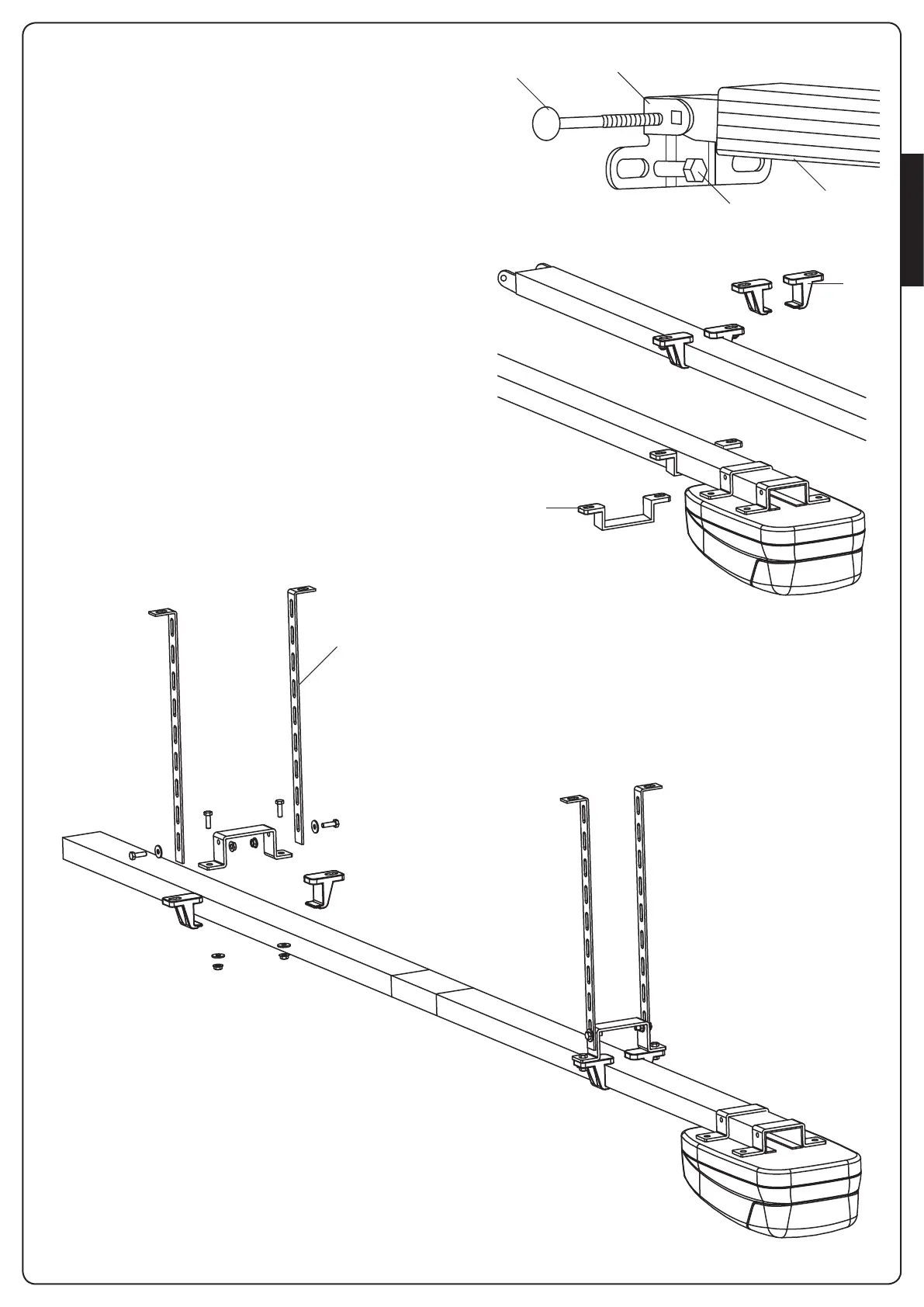
3. Fasten the bracket E to the upper crossbeam of the door using
plugs G suitable for the type of wall (ø minimum 8 mm).
4. Affix section A to the bracket using the 6x80 round-head
screw F and the self-locking nut provided.
5. Attach the two fixing supports H to section A, positioning
them approx. 1 m from the bracket E
6. Attach bracket I, positioning it close to the motor (approx. 5
cm)
7. Following the reference points previously traced out on the
ceiling, identify the fixing points for the supports H and the
bracket I; drill out the holes and using rawplugs suited to the
ceiling type (minimum diameter 8 mm), fix the automation
device.
8. Use the special drilled bars Q (accessory code 163203) should
it be necessary to adjust the height of the automation device.
Assemble the bars as shown in the following figure.
m PLEASE NOTE: the maximum distance between the
fixing piece and the ceiling must not exceed 300 mm