ENGLISH
33
CURRENT SENSOR LEVEL
T
o modify the current sensor level procede as follow:
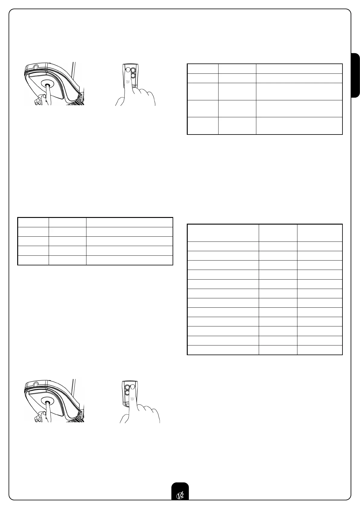
1. Press and keep pressed the key P1 for 5sec (courtesy light
ON) and at the same time transmit with the key 1 of the
t
ransmitter (the transmission must last 3 sec).
2. When the courtesy light switch off, stop the transmission
and release P1 key.
3. After 2 sec. the courtesy light visualizes the setted level with
the relative number of flashes. SEE CHART.
4. The courtesy light switch off for 2 sec. Then it goes on again
for 5 sec. waiting for a transmission.
5. Transmit (within 5sec) with the ideal key according to the
CHART.
6. The courtesy light switch off for 2 sec and therefore it
visualizes the new level setted with the relative number of
flashes. SEE CHART.
To correct any one of the parameters, restart from point 1.
FUNCTIONING LOGIC
To modify the functioning logic procede as follow:
WARNING: In case the photocell is connected the AUTOMA-
TIC logic can be selected; in case the photocell is not con-
nected it will work with the STEP BY STEP logic only.
The photocell TX must be connected to the proper termi-
nals for the check test 10 and 5.
1. Press and keep pressed the key P1 for 5sec (courtesy light
ON) and at the same time transmit with the key 2 of the
transmitter (the transmission must last 3 sec).
2. When the courtesy light switch off, stop the transmission
and release P1 key.
3. After 2 sec. the courtesy light visualizes the setted level with
the relative number of flashes. SEE CHART.
4. The courtesy light switch off for 2 sec. Then it goes on again
for 5 sec. waiting for a transmission.
+
K
ey 1
5 sec.
TX KEY FLASHING N° DESCRIPTION
Key 1 1 Level 1: Light door
Key 2 2 Level 2: Medium / light door
Key 3 3 Level 3: Medium / heavy door
Key 4 4 Level 4: Heavy door
5. Transmit (within 5sec) with the ideal key according to the
CHART.
6. The courtesy light switch off for 2 sec and therefore it
visualizes the new level setted with the relative number of
flashes. SEE CHART.
To correct any one of the parameters, restart from point 1.
STEP BY STEP LOGIC
The step by step logic enables the following cycle operation:
OPEN - STOP - CLOSE - STOP - OPEN
AUTOMATIC LOGIC
The automatic logic enables the automatic closing after a
setted time.
+
Key 2
5 sec.
TX KEY FLASHING N° DESCRIPTION
Key 1 1 STEP BY STEP Logic
Key 2 2
AUTOMATIC Logic
Pause time = 30 sec.
Key 3 3
AUTOMATIC Logic
Pause time = 1,5 min.
Key 4 4
AUTOMATIC Logic
Pause time = 3 min.
FUNCTIONING
STEP BY STEP
LOGIC
AUTOMATIC
LOGIC
Start in opening
STOP NOT PERCEIVED
Start in closing
STOP REVERSE
Start in pause
- CLOSE
Photocell in opening
NOT PERCEIVED NOT PERCEIVED
Photocell in closing
REVERSE REVERSE
Photocell in pause
- T.PAUSE RECHARGE
Current sensor in opening
STOP STOP
Current sensor in closing
REVERSE REVERSE
Stop in opening
STOP STOP
Stop in closing
STOP STOP
Safety rib in opening
REVERSE 3 sec REVERSE 3 sec
Safety rib in closing
REVERSE REVERSE