5
vacon • 74 Installation
Local contacts: http://drives.danfoss.com/danfoss-drives/local-contacts/
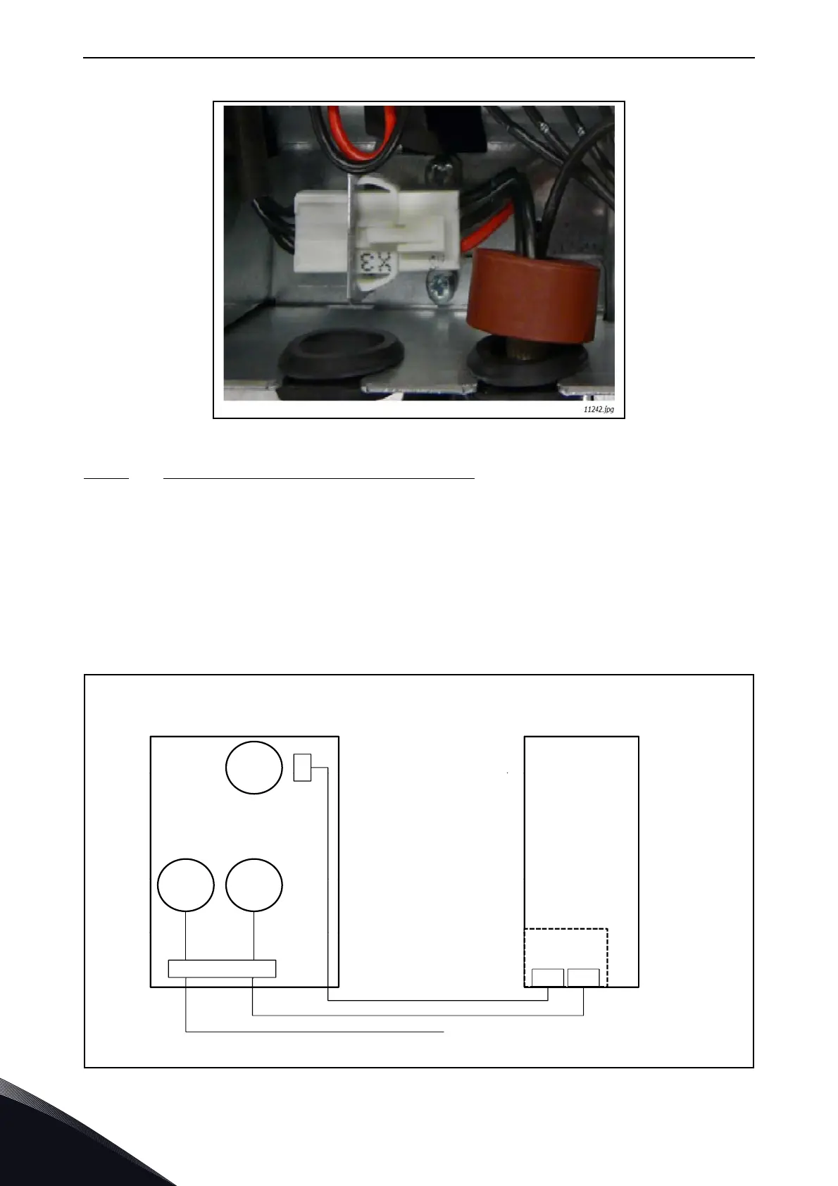
Figure 44. Terminal X3 (U-phase in FI13) in the unit
5.3.4.2
LCL filter without DC/DC power supply for fan
The LCL filter is supplied without an integrated DC/DC power supply. In this case, the customer
must procure the power supply separately. The requirements for the DC power supply are shown in
Table 5. Short-circuit protection is implemented by protecting the input of the DC power with fuses.
When required, the cooling fan can be controlled on/off by installing a contactor in the DC power
supply input and controlling that depending on whether the main switch is open or closed. The over-
temperature protection of the LCL filter must always be wired from contacts 1 and 4 of terminal X52
to a digital input of the control unit (see Appendix 85) and from contacts 1 and 2 of terminal X51 to a
digital input of the control unit. The wiring of the circuit is shown in Figure 45.
Figure 45. Wiring diagram of external DC-power
X51
DIN2 DIN3
11164.emf
LCL filter with external DC/DC supply
DC supply
(48 Vdc)
Control unit
AFE unitLCL filter
X51: (4-pin)
1 = Over-temperature
protection switch
2 = Over-temperature
protection switch
3 = DC- (supply)
4 = DC+ (supply)
X52: (4-pin)
1 = Over-temperature
protection switch
4 = Over-temperature
protection switch
Tempe-
rature
Switch
Tempe-
rature
Switch
Fan
M
Over-tempera-
ture protection
Over-
temperature
protection
 Loading...


