3.4 Attaching Probes and Cables
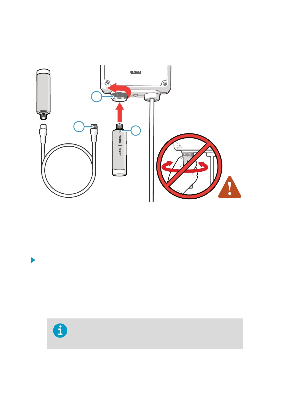
Figure 12 Attaching Probes and Cables to Indigo
1 Insert probes into the probe connector with the orientation mark facing out.
2 Probes are locked in place with the locking wheel. Never turn from the probe body.
3 Connect probe cables in the same way as probes: insert the cable in the connector and
hold in place while turning the locking wheel.
1. Insert the probe into the probe connector with the orientation mark on the probe body
facing out.
2. Hold the probe in the probe connector and lock it in place by turning the locking wheel
counterclockwise. Do not turn the probe body when attaching, only the locking wheel
on the transmitter.
3. If no previous
configuration exists (that is, this is the first time a probe is connected to
Indigo, and no configuration has been set manually), Indigo adapts the analog output
settings of the connected Vaisala Indigo-compatible probe automatically.
If a
configuration that diers from the attached probe's configuration exists in the
transmitter, you must configure the new probe manually to enable analog output.
See Receiving Analog Output Settings from Probe (page 16).
Indigo 201 User Guide M211877EN-E
20