VAMP Ltd Feeder and motor manager
Technical description
VAMP 257
VM257.EN002 VAMP 24h support phone : +358 (0)20 753 3264
69
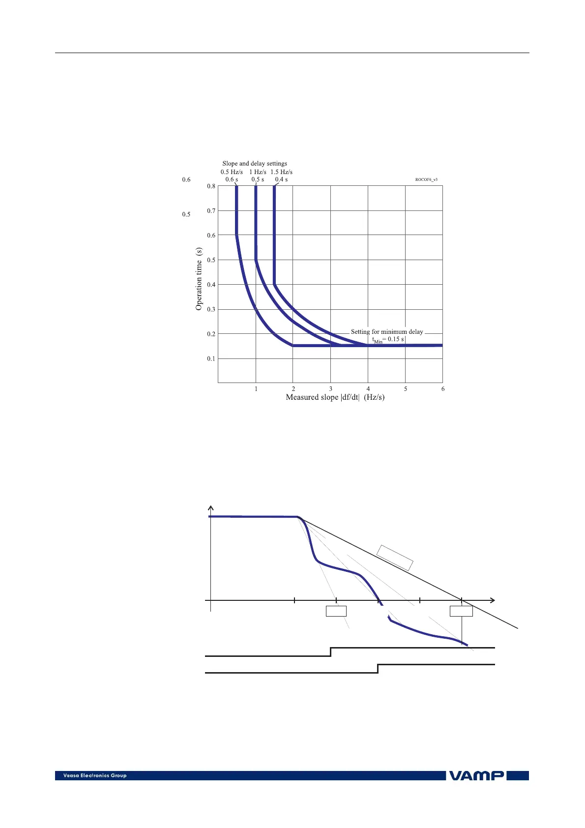
The minimum operation time is always limited by the setting
parameter t
Min
. In the example of Figure 2.3.22-4 the fastest
operation time, 0.15 s, is achieved when the slope is 2 Hz/s or
more. The leftmost curve in Figure 2.3.22-3 shows the inverse
characteristics with the same settings as in Figure 2.3.22-4.
Figure 2.3.22-3 Three examples of possible inverse df/dt operation time
characteristics. The slope and operation delay settings define the knee
points on the left. A common setting for t
Min
has been used in these three
examples. This minimum delay parameter defines the knee point positions
on the right.
0.75 Hz/s
2.0 Hz/s
FREQUENCY
(Hz)
49.7
START
TRIP
Settings:
df/dt = 0.5 Hz/s
t=0.60s
t=0.15 s
Min
0.00 0.450.30
50.0
TIME
(s)
ROCOF3_v3
1.0 Hz/s
0.5Hz/s
0.15 0.60
Figure 2.3.22-4 An example of inverse df/dt operation time. The time to trip
will be 0.3 s, although the setting is 0.6 s, because the average slope 1 Hz/s
is steeper than the setting value 0.5 Hz/s.