VAMP Ltd Feeder and motor manager
Technical description
VAMP 257
VM257.EN002 VAMP 24h support phone : +358 (0)20 753 3264
57
Parameter Value Unit Description
Shot# 1 … 5 -
The
currently
running shot
ReclT RECLAIMTIME;
STARTTIME;
DEADTIME;
DISCRIMINATIONTIME
-
The
currently
running time
(or last
executed)
SCntr -
Total start
counter
Fail -
The counter
for failed AR
shots
Shot1 * -
Shot1 start
counter
Shot2 * -
Shot2 start
counter
Shot3 * -
Shot3 start
counter
Shot4 * -
Shot4 start
counter
Measured
or
recorded
values
Shot5 * -
Shot5 start
counter
*) There are 5 counters available for each one of the four AR signals.
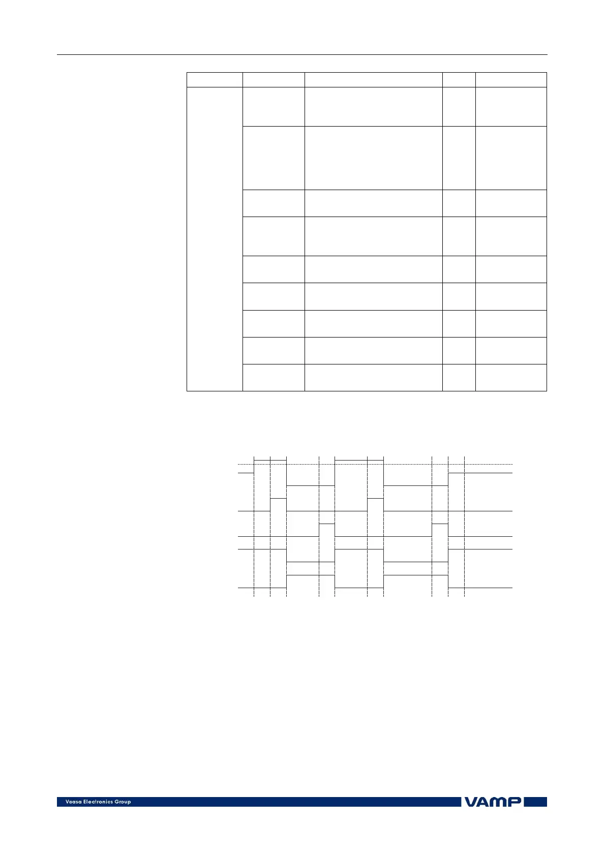
Current
Start delay1
Dead Time1
Dead Time2
Discrimination
time1
Discrimination
time2
Reclaim
time
Open CB
Close CB
CBopen state
CBclose state
I> setting
123
4
5
6
7
8910
AR signals
Figure 2.3.16-2. Example sequence of two shots. After shot 2 the fault is
cleared.
1. Current exceeds the I> setting; the start delay from shot 1
starts.
2. After the start delay, an OpenCB relay output closes.
3. A CB opens. The dead time from shot 1 starts, and the
OpenCB relay output opens.
4. The dead time from shot 1 runs out; a CloseCB output
relay closes.