Introduction VaporTEK Pump Characteristics
12
VaporTEK Valve Adapter Interface Kit - P/N 900XXX-001
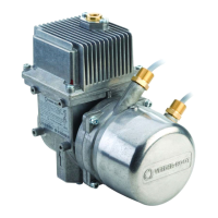
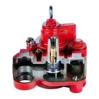
VaporTEK Pump Characteristics
1. The VaporTEK Pump is driven by the VaporTEK Controller.
2. The VaporTEK Pump has integrated flame arrestors at the inlet and outlet ports that prevent flame
transmission.
3. The inlet/outlet ports have standard G ¼” female threads (ISO – 228-1).
WARNING! DO NOT remove the flame arrestors. DO NOT install piping which can stress the pump
housing.
4. Vapor flow is from the nozzle through the vapor pump to the UST (See Figure 3 for flow direction).
5. The following conditions must apply according to EN13463-1 for the maximum pipe and hose lengths
between the nozzle and the VaporTEK Pump.
a. An inner diameter
10mm in the coaxial hose of length 6m, OR
b. Coaxial hose of length
6m with an outer diameter 38mm together with a DN15 pipe (G ½”),
length
3m.
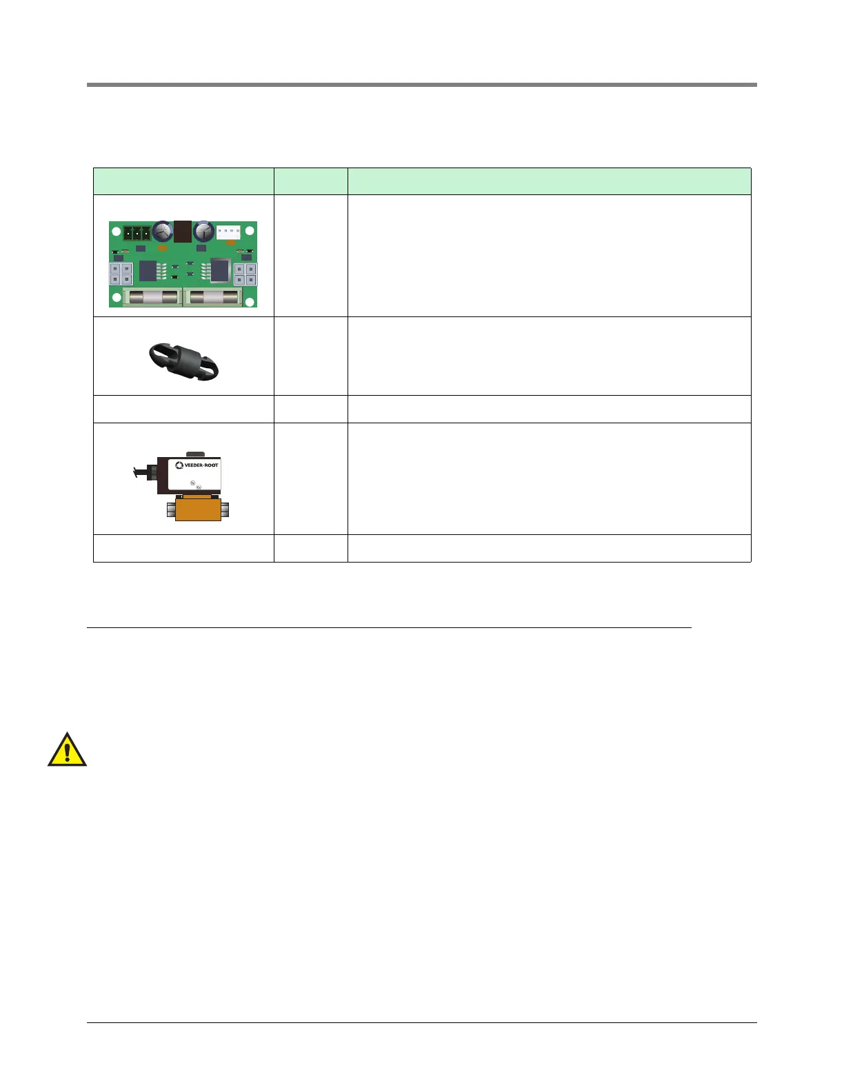
Quantity Description
1 VaporTEK – Valve Adapter Board P/N –SK 141 085 646
4 Support Post, Dual Locking M4.0 X 6MM LG (Plastic), P/N 579081-001
1 Cable, 4 wire
2EPV10
1Cable 24VDC
VEEDER-ROOT
VTEK3-EPV-
ADAPTER
141085646
A B 0V 5Vout
X2
X1
F1 F3
SIDE B
SIDE A
Duncansville,PA.16
Type: EPV10
SIRA 12ATEX6058X -40°
Valve: II 1/2G c T3
Solenoid: II 2G Ex MB