44
VaporTEK Calibration
Refer to dispenser manufacturer’s manual for VaporTEK system commissioning before
conducting the A/L calibration procedure.
Manual Calibration Using The Speed Setup If High Voltage Signals M1 And M2
Are Used
Check the dispenser flow rate during a real transaction on the highest nozzle clip. Setup the speed to M1 or M2 in
order to achieve the same vapor flow rate (A/L = 100%) using the sub item “2. Set config”.
Dry Calibration - A/L Adjustment
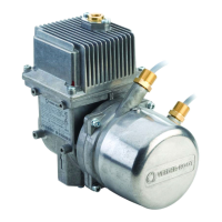
A/L adjustment using automatic dry calibration can be performed only with the VaporTEK Plus or VaporTEK Ultra
configurations.
Equipment Required
• FB1 hand held terminal with 15-pin to RS422 cable
• Gas meter
• A/L nozzle adapter (varies by nozzle manufacturer)
•Hoses
Initial Setup
1. Verify power is available at the VaporTEK-3 Controller board, both the V1 and V6 red LED’s are on and the V3
green LED is flashing slowly.
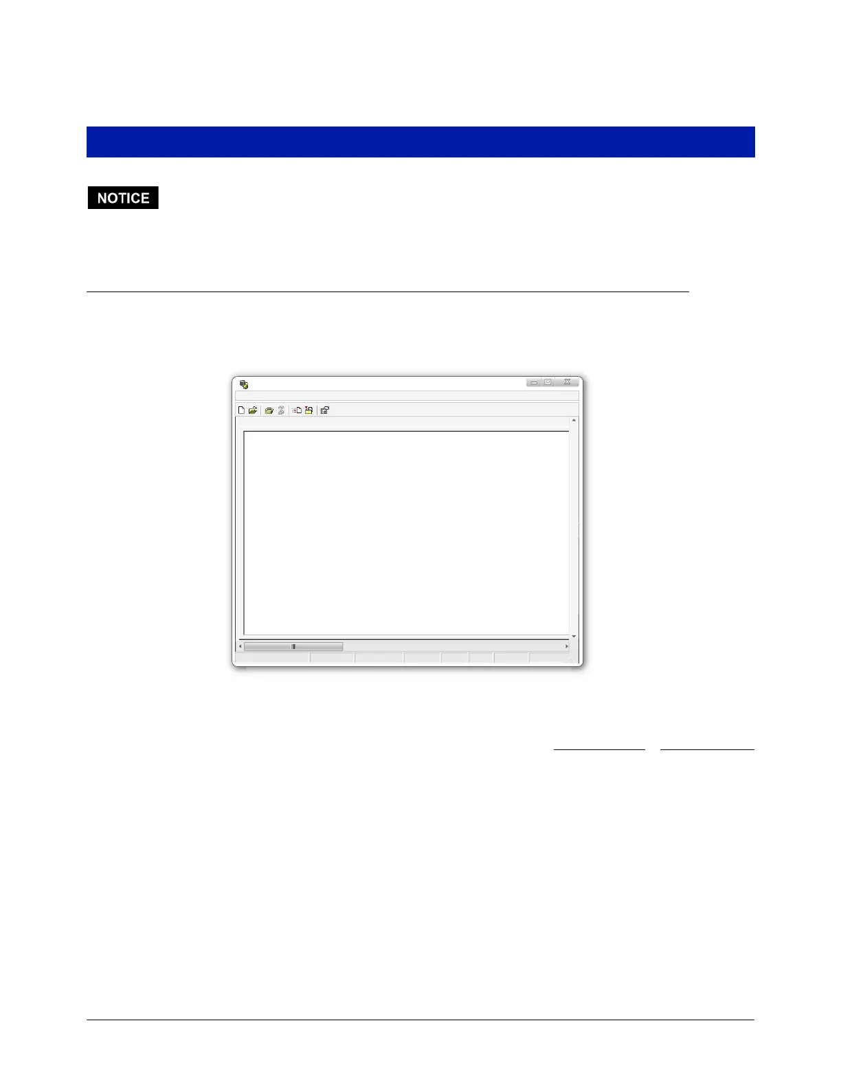
New Connection Hyperterminal
File Edit View Call Transfer Help
Print echoCaptureNUMCAPSSCROLL9600-8-N-1Auto detectConnected 0:02:44
2. Set Config
-------------
Pump Motor Type: VaporTEK
VTEK-RS422 Type: Slave Device
HV Nozzle Speed: M1 = 2500 rpm
HV Nozzle Speed: M2 = 2500 rpm
Set M1 - Input performance (0...250rpm x10):100
Set M2 - Input performance (0...250rpm x10):100
Do you want to save it?[Y/N]: y
Config has been stored successfully
Pump Motor Type: VaporTEK
VTEK-RS422 Type: Slave Device
HV Nozzle Speed: M1 = 1000 rpm
HV Nozzle Speed: M2 = 1000 rpm