34
Communication Setup - VaporTEK Interface
Setup with Laptop
Switch off, tag, and lockout the 230V AC Main power to the VaporTEK-3 Controller board and wait at least 30
seconds for it to power down.
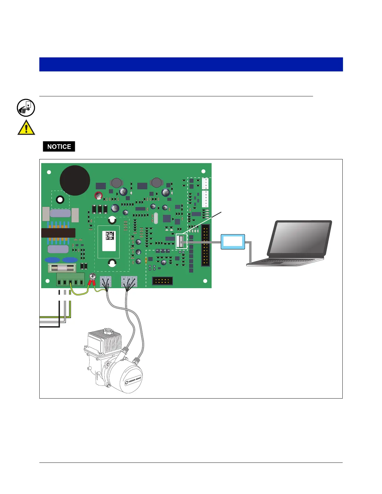
Connect your laptop to the VaporTEK-3 Controller board using the special USB Adapter flash adapter P/N: 141
057 636 as it’s shown in Figure 22.
All necessary setup, such as pulse ratio and K-Factor, can be done by using a FB1-Service
Terminal.
Figure 22. VaporTEK USB-Adapter Service
VEEDER-ROOT
VAPORTEK-CONTROLLER
900890-001
Rev.C
P/N 141 031 916
S/N 0000586
DATE 49/2016
RoHS Compliant
PE
F1
PE
L N PE M1 M2
+ - AB SB AA SA EPV VALVE
MOTOR
POWER
MOTOR
SIGNAL
J3
V6
V3 V8
V1
X7
X6
X8
PROGRAM
J1
J2
X3X2
X1
X4
BR1
IC5
RS422
UNSAFE AREA
UNSAFE AREA
SAFE AREA
L1
USB Service and Flash
Adapter cable plugs into
PROGRAM connector
NPE
M1 M2
VTEK3 Flash
Adapter