Wiring Schematics VaporTEK Wiring
31
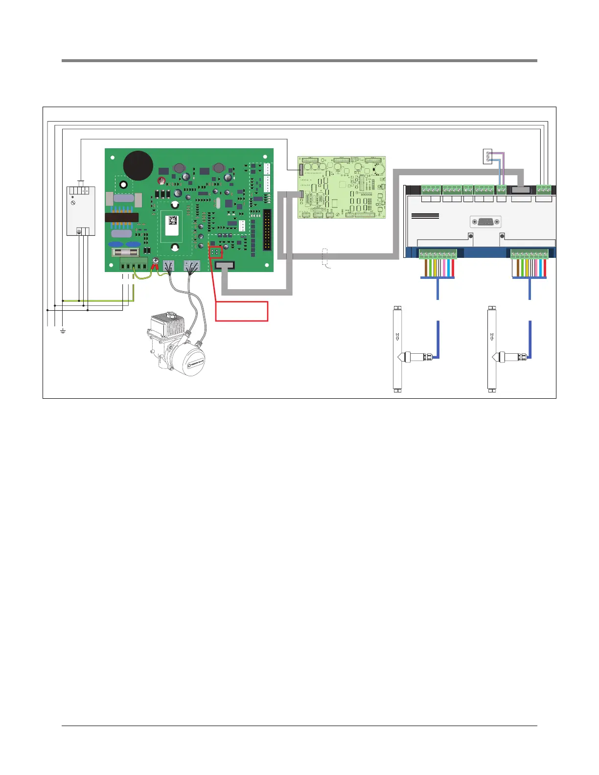
Figure 18.
VaporTEK System – Serial Connection And Monitoring Using RS422 – Interface With Re-regulation Function.
6. VaporTEK with low Voltage hook signal with relay switches (see Figure 16)
a. Refer to the dispenser manufacturer’s manual to determine the dispenser type (Blended or Multi-product),
the number of available nozzle hooks and where to tap them (Verify the hook signal voltage rating is 220/
240 VAC).
b. Using the 18AWG, 2 conductor cable from the kit, connect each nozzle hook signal on Side A of the
dispenser to one high voltage relay circuit.
c. A High Voltage source (110-230VAC) is connected to the M1 on the VaporTEK Controller through all the
relay circuits on Side A (See Figure 18 for high voltage relay wiring diagrams).
d. Make similar connections on Side B and connect to M2 on the VaporTEK Controller.
-B+ -A+
Pulse Out B
-2 + -1+ - +
Out A 5 V
B A
BA12345678 12345678
PE N L
RS485 230 V~ RS485-4
- 2+ -1+
FAFNIR
VAPORIX - Control
Service
VAPORIX Flow -
SIDE A
VEEDER-ROOT
VAPORTEK-CONTROLLER
900890-001
Rev.C
P/N 141 031 916
S/N 0000586
DATE 49/2016
RoHS Compliant
PE
F1
PE
L N PE M1 M2
+ - AB SB AA SA EPV VALVE
MOTOR
POWER
MOTOR
SIGNAL
J3
V6
V3 V8
V1
X7
X6
X8
PROGRAM
J1
J2
X3X2
X1
X4
BR1
IC5
RS422
UNSAFE AREA
UNSAFE AREA
SAFE AREA
L1 N
MAIN
230V
L1 N PE
M1 M2
PULS
Power Supply
100W
140 810 856
24V
DC
OK
LN
++
VAPORIX Flow -
SIDE B
VRC RS422
P6015
P6001 PSU AND BBM
E101 CPU
RS485
Interface
Standard RS422
10-pin ribbon cable
Gilbarco CPU Board E101
M06104
Optional
Kiosk Alarm Indicator
Jumpers J1 and J2
are not used in this
conguration.