Introduction VaporTEK Valve Adapter Board (Optional)
16
Jumper J1/J2 defines the function on P4A / P4B input. A placement on position 1-2 sets the P4 input as pulse
train input. With a placement on position 2-3 the P4 input is used as a Diesel - disable input. In this mode all pulse
train inputs will be disabled if the voltage on P4 – Input is higher than 2.5V DC.
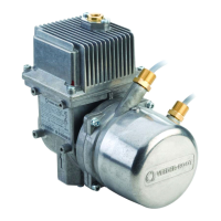
VaporTEK Valve Adapter Board (Optional)
The VaporTEK-3 – Controller Board, Rev. C, provides a dedicated output to the VaporTEK Valve Adapter board. A
pulse wide modulated (PWM) signal is used to control the valve power for each side separately. An on-board
integrated current regulator is stabilizing the valve current against temperature drift on the valve solenoid head.
An equalizer setup function provided by the FB1 – Service terminal (with software version 6.9 and above) allows
the service technician to calibrate the valve power in dual transaction mode. This setup can also be done using a
laptop along with the USB Service/ Flash – Adapter. Two setup points for each valve will be used to calibrate the
valve curve. During a single side transaction the EPV’s are controlled in ON/OFF - Mode.
Washers with 3mm orifice used to avoid ghost transaction on the Vaporix Monitoring can be omitted in this
configuration.