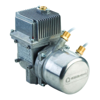
Introduction VaporTEK Pump Configuration
18
VaporTEK Pump Configuration
The VaporTEK Pump can be configured to operate in either a 2-Speed or a Variable-speed mode depending on
the configuration type and available dispenser inputs/signals.
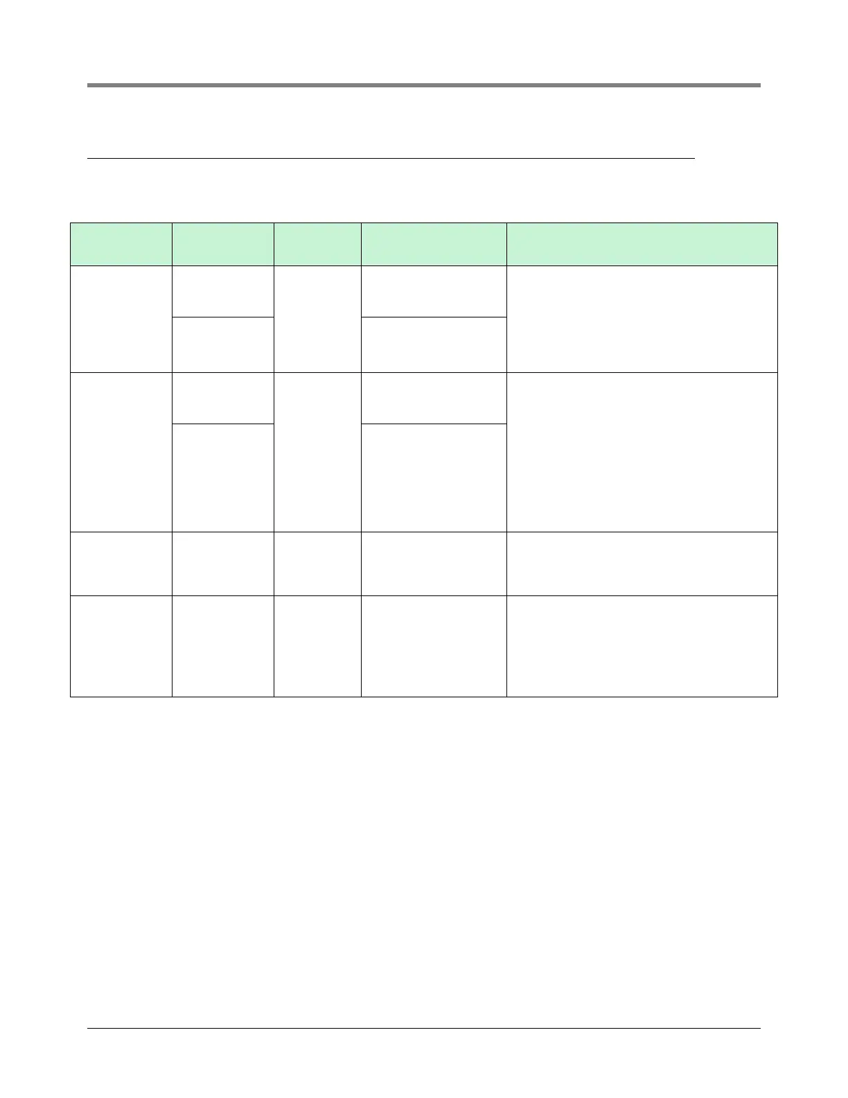
VaporTEK
Configuration
Input Type
Mode of
Operation
Required
Components
Method of Operation
Basic
High voltage
hook signal
(110-240VAC)
Two Speed
VaporTEK-3 Controller
The VaporTEK Controller receives nozzle hook
signals from either side of the dispenser.
With one fueling point active, the pump operates
in low speed. With two fueling points active, the
pump operates in high speed.
Low voltage
hook signal
(0-24VDC)
VaporTEK-3 Controller,
High Voltage Relay
Enhanced
High voltage
hook signal
(110-240VAC)
Two Speed
VaporTEK-3 Controller,
MPV10
In this configuration a high voltage hook signal
from either side of the dispenser operates a
relay switch which in turn control’s the high volt-
age input to the Vapor TEK Controller.
Note: One relay switch is required for each
gasoline nozzle in the dispenser.
With one fueling point active, the pump operates
in low speed. With two fueling points active, the
pump operates in high speed. This configuration
is typically used for multi-product dispensers
with low voltage hook signals.
Low voltage
hook signal
(0-24VDC)
VaporTEK-3 Controller,
MPV10,
High Voltage Relay
Plus
Liquid pulse
signal or serial
communication
line
Variable
Speed
VaporTEK-3 Controller,
Pulse Interface
(optional)
VaporTEK-3 Controller receives the fuel flow
information via serial data line or calculates the
flow value using pulse inputs. This value will be
used to control the motor speed.
Ultra
Liquid pulse
signal or serial
communication
line
Variable
Speed
VaporTEK-3 Controller,
Valve Interface and EPV
10
Pulse Interface
(optional)
VaporTEK-3 Controller receives the fuel flow
information via serial data line or calculates the
flow value using pulse inputs. This value will be
used to control the motor speed. An additional
connected Valve Interface along with two EPV’s
controls the A/L – Ration during a simultane-
ously transaction.