EasyManua.ls Logo

Veeder-Root VaporTEK - Simulation with FB1 Terminal; Executing Simulation Steps

Veeder-Root VaporTEK
58 pages
To Next Page IconTo Next Page
To Previous Page IconTo Previous Page
Loading...
A-1
Appendix A: VaporTEK System Reference Wiring Diagrams
Figure A-1. VaporTEK Plus For Collection - Encore 500S With VaporTEK-3 Controller
VEEDER-ROOT
VAPORTEK-CONTROLLER
900890-001
Rev.C
P/N 141 031 916
S/N 0000586
DATE 49/2016
RoHS Compliant
PE
F1
PE
L N PE M1 M2
+ - AB SB AA SA EPV VALVE
MOTOR
POWER
MOTOR
SIGNAL
J3
V6
V3 V8
V1
X7
X6
X8
PROGRAM
J1
J2
X3X2
X1
X4
BR1
IC5
RS422
UNSAFE AREA
UNSAFE AREA
SAFE AREA
L1 N PE
M1 M2
Gilbarco, Inc.
24V 135W
TB3
P2
TB3
J1
FB1 Service
Terminal
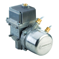
VaporTEK Pump
VaporTEK 3 Controller Board (900890-001)
VAPOR VA CCASH (A) TRIND SMRT CASH (B)
Plug the orange
connector into any
connector on the
M04406A001 cable
230V
230V
F6
F1
F8
F3
Home
7
END
1
SHIFT SPACE ENTER
INS
0
+
2
PgDn
3
4
5
6
PgUp
9
8
F9
F4
F10
F5
F7
F2
START
VTEK3 Flash
Adapter

Table of Contents

Other manuals for Veeder-Root VaporTEK

Related product manuals